Thermowell as simple as it looks requires a lot of consideration with respect to Wake frequency calculation, material selection, etc.
Installing a Thermowell near upstream of a pump is not recommended unless there is a dire need to do so.
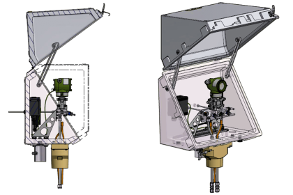
Thermowell Installation

(Standards like PIP PCSPS001 in section 4.6.5.1 suggest that thermowells shall not be located between suction screens and inlets of pumps, compressors, or turbines)
In such cases, it is not mandatory but recommended to install a thermowell on an elbow (A safety margin for below-listed errors) as compared to perpendicular thermowell installation near such critical cases.
But every recommendation must have a reason, the following are the factors that empower this elbow installation near pump upstream, etc.
The wake frequency calculation as per ASME PTC 19.3 does not cover every case.
The analysis of thermowell response to fluid flow in ASME PTC 19.3 presumes a steady fluid velocity.
Pulsating flows where the fluid velocity varies at a frequency close to the natural frequency of the thermowell can also excite thermowell vibrations.
Thermowell failures have been attributed to the exposure of a thermowell to pulsating fluid flow.
(e.g:-thermowell failures have been seen for installations close to the discharge of a centrifugal pump)
Reference:- ASME PTC 19.3 Section 6-3.7 page 14.
Hence if we install a perpendicular thermowell and do the Wake frequency calculation, we still can’t rest assured that everything will work out ideally.
Is the Velocity given to you accurate?
Sometimes velocity given to us could be put to question.
Velocity changes due to reducer or blower added to a line at end-stage could get missed out.
And note that the area change impacts the velocity.
Refer below diagram

So the Velocity provided by the Process department might be for the Higher line size and during later stages, a reducer or blower was added.
This impacts the velocity consideration and the process department must be informed to provided updated velocity considerations.
Miscellaneous Errors
While building a bridge, the bridge is designed for handling weight far superior to its requirement.
This is done because this acts as a “Safety margin” for unforeseen errors or factors that had to be considered like abnormal weather considerations etc.
Similarly when installing near pump upstream or other such critical places if due to unanticipated circumstances the thermowell fails and breaks near such critical places the failure could be catastrophic.
Like the pump was changed due to higher capacity requirement but the thermowell was not changed etc.
Hence It’s better to achieve a safety margin for such unanticipated scenarios and install at an elbow which has far less probability to fail under stress.
And then evaluate the Thermowell case (even though it is installed in an elbow) as a perpendicular case.
Thanks for reading.
I hope it’s been of value to you.
PS: This is as per the best of my current understanding. I would be indebted to know if any corrections or updates are required.
Author: Asad Shaikh
Profile: Linkedin
Read Next:
- Thermowell Types in Industries
- Design Guide of Thermowells
- Wake Frequency Calculation
- Thermowell Insulation Thickness
- Selection of Thermowells