What are the major sources of error in a Thermocouple (TC) measurement?
Basically a TC behaves in a very predictable manner – it either works or it does not work. That being said, there are a few things that come up over and over that make it not work.
In short there are four major reasons that you will get errors in your TC Measurement:
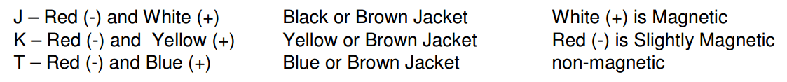
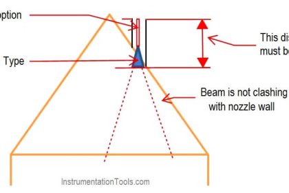
1) Selecting the wrong TC type –
The TC type selection in the transmitter must always match the TC being used. This kind of error happens a lot. Different TC’s have different curves, different ranges, and different mV outputs, so everything has to match. The most common types are J, K, and T. 1 Since TC’s are color coded it is easy to check:
2) The TC junction error –
TC’s have an inherent error due to the fact that the alloys are not perfect. They vary slightly from batch to batch production. Since you are dealing with micro-volts it doesn’t take much to be off a little. Standard TC’s are typically about 1% of the measured temperature at the junction. Special limits are twice as accurate, triple limits 4 times as accurate. 1 Your accuracy is therefore limited to the accuracy of the TC junction. There is not much you can do about this error, except specify special limits.
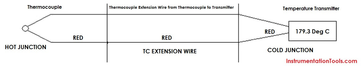
3) The connection to the TC extension wire is another major source of error.
Note that the red wire is shown above. If the TC extension wire is installed backwards, the TC will still work. It will just be wrong by the difference in the temperature of the two ends of the extension wire. Don’t laugh. We have seen this many times.
The TC extension wire has to match the TC type. It must be respective TC wire, not copper
Don’t run TC extension wire in excessively hot or cold environments. It is only rated from 0°C to 200°C (-60°to + 100°C for type T)
Another source of error is a poor thermal connection, the use of uncompensated barrier strips, and wire nuts. The TC material should be joined to the TC material, not to a barrier strip. If you are going to use a barrier strip put the TC wires under the same screw, or order TC material terminal lugs. If you use wire nuts, twist the TC wires together first. Type J will often break (sooner or later) when you twist it. If you don’t care about 2°-3°, you don’t need to worry about TC lugs.
If you are looking for extreme accuracy, don’t use TC extension wire. Run the entire length with the original TC wire. TC extension wire is only designed for the accuracy of standard TC wire. Each time you make a transition to a new piece of TC wire, you add the TC error all over again. Be careful in lab applications to use one length of wire.
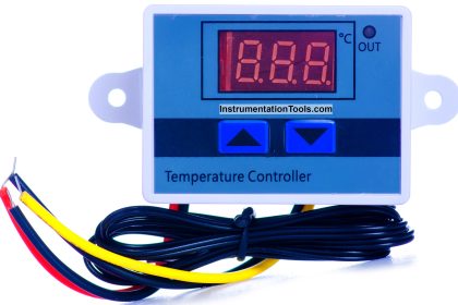
Last you can use a TC transmitter. These guys have fallen in price to the $ 150 range. The transmitter converts, compensates and linearizes the TC at the source, eliminating the TC extension wire. Most TC transmitters supply 4 – 20 mA over the span of interest.
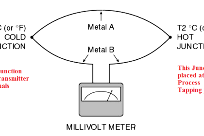
4) The other significant source of error is the cold junction compensation
TC’s measure the difference in the temperature at the two ends. Thus the more accurately you can measure the cold junction the more accurately you can measure the TC. Cold junctions are often specified at 1°or 2°.
Although the cold junction spec may be OK, how you hook to the cold junction is another issue. You should bring the TC into the meter with a small loop of wire near the meter. The idea is to cause the TC to be close to the meter’s temperature at the cold junction. Fans or heat sources near the TC hook-up to the meter can create large errors due to temperature differentials. Sometimes a small piece of foam over the TC terminals can make a big difference.
In order to find the accuracy of your TC, you have to add up all of the errors. Some you can improve, some are just the nature of the beast. Keep in mind that the TC measures temperature along its entire run,
By the way, a couple of quick tests to make sure the TC is hooked up right – put your hand around it. The temperature should go up. If it goes down, it is backwards. If you short a TC it will read room temperature.
Also Read: Difference between Thermocouple & RTD


Sir what is generally used as industrial standard output for TC microvolt or millivolt ?
and since output of TC are very small how it is distinguished from the error generated from the transmitter of TC which is comparable to its output ?
Nicely covered important aspects of TCs, Their geometry, shape, size and type of insulation used both at the junction and rest of the length matters. Accidental contact with metallic surrounding/ground matters a lot could drastically change the measured value. TCs to be used are to be selected based on the type fluid, range of the temperature and the biggest concern is desired uniformity of the temperature , in case of environment chambers/ovens the location of control TC matters a lot unless a blower fan is used to maintain uniformity. In case of high temperature furnaces over 1400 degrees Celsius the condition of the zone is important draft and vibration conditions are to be avoided to extend the life of the TCs.
I agree with you
how long can I extend the cable to tc penytu to have no errors, and with what type of cable