The first thing to do after purchasing a new device is to test it and install it in the field if it is OK.
The main purpose of this post is to discuss the testing procedure of my today’s device Thermal Protection Relay.
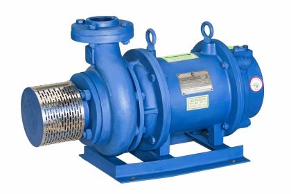
The thermistor-protected three-phase induction motor has a total of three PTC thermistors in each of the windings which are connected to the terminal block by two cables connected to each other in series (follow Figure 1).
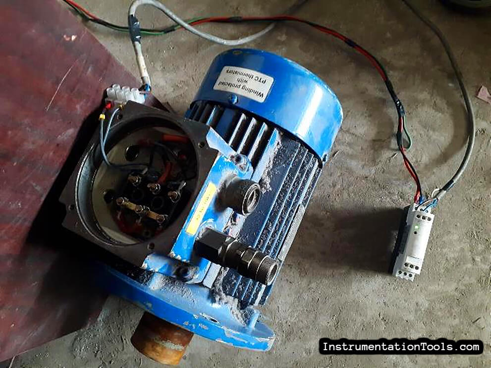
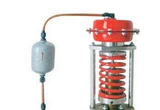
Thermal Protection Relay for Motors
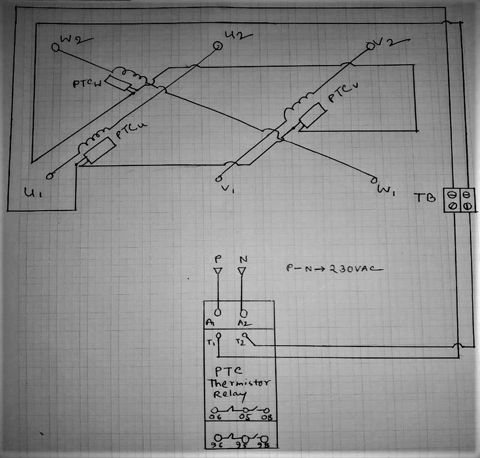
For the purpose of testing, I connected two cables from the terminal block of the motor to the T1, T2 terminal of the reel as per Figure 1. Then I did the wiring for the coil supply voltage at relay A1, A2 terminal, I had this relay 230VAC coil.
Before turning on the coil supply, I checked the resistance at the T1, T2 terminal with a multimeter to see if the thermistor connection was working properly, I got a reading of 285 ohms (this is the value) Now come to auxiliary contact.
These types of protection devices usually have the Fail-Safe feature, meaning that the device will automatically change its status from normal to auxiliary if the device is faulty or dead.
So before turning on the coil supply I found the NO contacts of the relay in closed condition and the NC contacts in open condition – meaning if there is a thermal fault in the motor then the auxiliary contact will be in the same condition as in the device dead. That means the device is OK.
This time after turning ON the coil supply, the green indicator flashed and NO contact was opened and NC contact was found closed, which means that it is OK in normal operation. (check the relay status indicators on the above image)
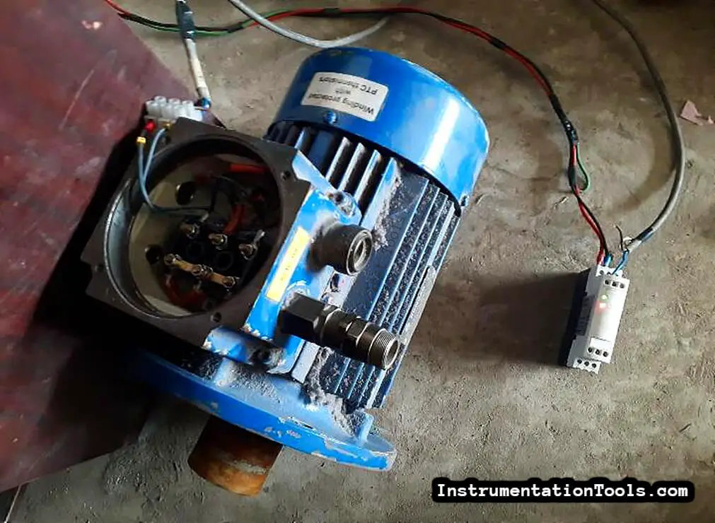
Now the fault is lit by manually creating a fault by disconnecting the cable from the T1 terminal and the NO and NC contacts are closed and open, respectively. (check the relay status indicators on the above image)
Some of these relays are also available with a test button that can be pressed to check the functionality of a regular device.
… thank you all …
Author:

Electrical Engineering professional with 10+ years of experience in industrial automation and maintenance activities. Worked at different manufacturing facilities and process plants along with experience of erection, commissioning of LPG filling process plant.


Sorry. As I see your explanation about the relay and from what I know, if we give power to the coil of relay, the status of NO contact will be closed and the status of NC contact will be opened. I think you made some wrong explain about the operation principles of relay
This will happen (like you said) when thermal breakdown of windings will happen inside motor or the thermistor wires are broken (both along with coil supply power on) or device power is dead…
But in healthy condition along with coil supply power on, contacts won’t change their states.
Thank you…