Inst ToolsInst ToolsInst Tools
  • Courses
  • Automation
    • PLC
    • Control System
    • Safety System
    • Communication
    • Fire & Gas System
  • Instrumentation
    • Design
    • Pressure
    • Temperature
    • Flow
    • Level
    • Vibration
    • Analyzer
    • Control Valve
    • Switch
    • Calibration
    • Erection & Commissioning
  • Interview
    • Instrumentation
    • Electrical
    • Electronics
    • Practical
  • Q&A
    • Instrumentation
    • Control System
    • Electrical
    • Electronics
    • Analog Electronics
    • Digital Electronics
    • Power Electronics
    • Microprocessor
Search
  • Books
  • Software
  • Projects
  • Process
  • Tools
  • Basics
  • Formula
  • Power Plant
  • Root Cause Analysis
  • Electrical Basics
  • Animation
  • Standards
  • 4-20 mA Course
  • Siemens PLC Course
Reading: Test and Process Modes in Siemens PLC
Share
Notification Show More
Font ResizerAa
Inst ToolsInst Tools
Font ResizerAa
  • Courses
  • Design
  • PLC
  • Interview
  • Control System
Search
  • Courses
  • Automation
    • PLC
    • Control System
    • Safety System
    • Communication
    • Fire & Gas System
  • Instrumentation
    • Design
    • Pressure
    • Temperature
    • Flow
    • Level
    • Vibration
    • Analyzer
    • Control Valve
    • Switch
    • Calibration
    • Erection & Commissioning
  • Interview
    • Instrumentation
    • Electrical
    • Electronics
    • Practical
  • Q&A
    • Instrumentation
    • Control System
    • Electrical
    • Electronics
    • Analog Electronics
    • Digital Electronics
    • Power Electronics
    • Microprocessor
Follow US
All rights reserved. Reproduction in whole or in part without written permission is prohibited.
Inst Tools > Blog > PLC Tutorials > Test and Process Modes in Siemens PLC

Test and Process Modes in Siemens PLC

In this article, we will learn about a term test and process modes reside in the TIA PORTAL software of Siemens PLC.

Last updated: March 4, 2021 11:21 am
Editorial Staff
PLC Tutorials
No Comments
Share
3 Min Read
SHARE

In this article, we will learn about a term test and process mode reside in the TIA PORTAL software.

Contents
Test and Process ModesTest Mode:Process Mode:

These two options you may find in some PLC and not in every PLC. It depends on the type of PLC you choose.

Test and Process Modes

Let’s find out where these functions are residing in the PLC software.

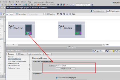
Open TIA PORTAL. Go to “Device and Network”.

Siemens PLC Device and Network

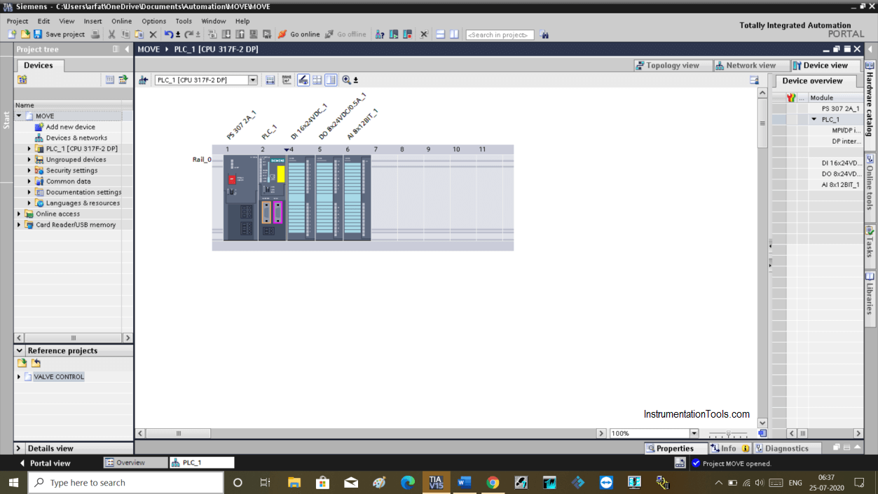
Now, select the CPU and go to the “properties tab”. This is a safety CPU which contains operating mode.

Here, in the “general” tab section you can find “operating mode” as you can see in the below window.

Siemens Test Mode

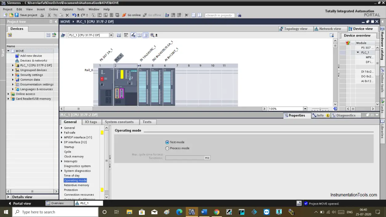
Inside operating mode, you can find two options

1. Process mode
2. Test mode

Selection by default comes in test mode.

Test Mode:

As you can see in the above window that selection is at by default test mode.

In test mode you can perform test functions means you can modify and monitor variables.

In the test function, you can perform every function without any restrictions.

But it requires greater scan time. So, if a user program is in test mode then it must have a larger scan time.

In case you find trouble using modify and monitoring that means selection is made to process mode.

Process Mode:

As you can see in the below window that selection is now made to Process mode.

Siemens Process Mode

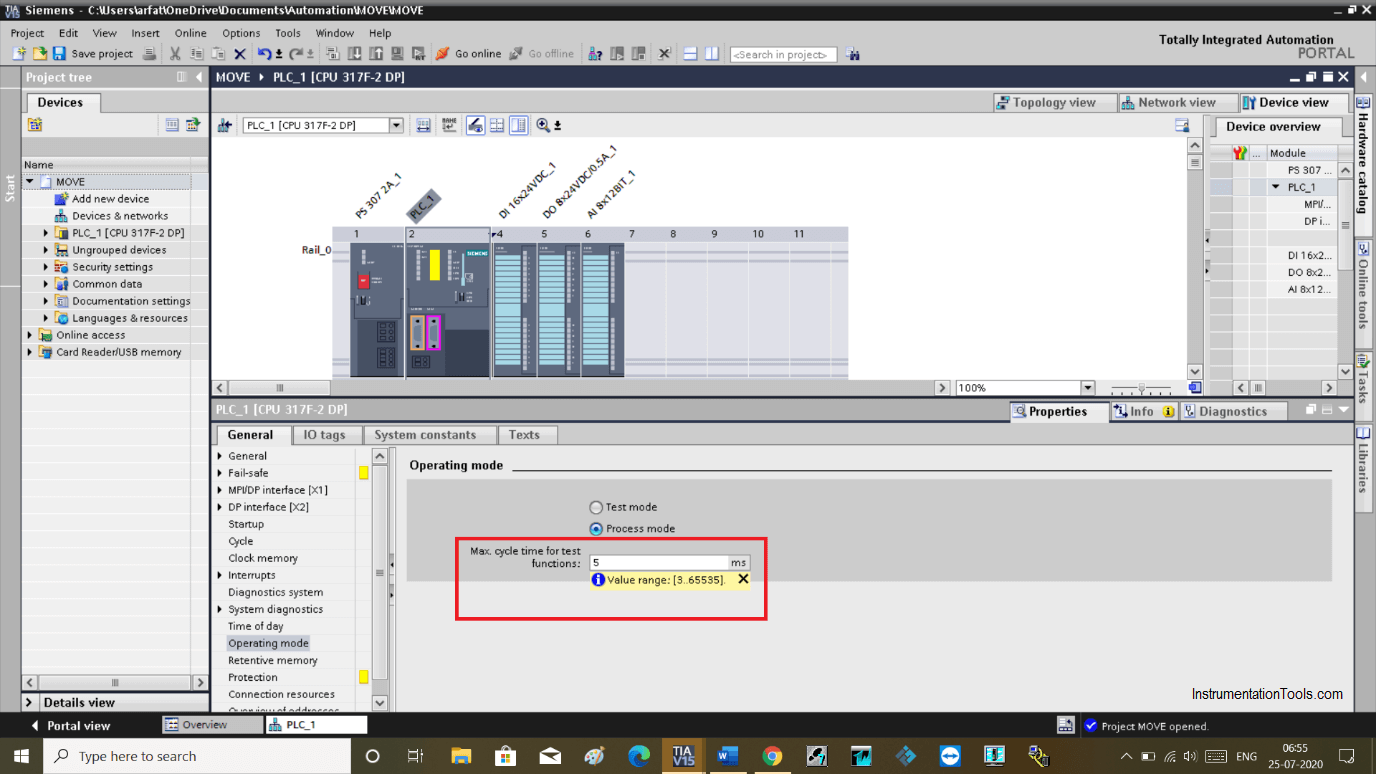
Here, you can change the cycle time. You can set a cycle time between 5 and 65535 ms.

It restricts modify and monitor function to reduce cycle time.

Step by step programming execution can’t be performed.

No call condition is permitted to make sure that scan time can’t exceed the set cycle time.

It won’t allow changes to be made in the programming environment.

Author: Suhel Patel

If you liked this article, then please subscribe to our YouTube Channel for PLC and SCADA video tutorials.

You can also follow us on Facebook and Twitter to receive daily updates.

Read Next:

  • Siemens CPU Execution
  • Factory Acceptance Test
  • Run Motors in Sequential
  • Allen Bradley Architecture
  • Save PLC Project to Card
Don't Miss Our Updates
Be the first to get exclusive content straight to your email.
We promise not to spam you. You can unsubscribe at any time.
Invalid email address
You've successfully subscribed !

Continue Reading

Electric Motor Forward Reverse with Repeat Cycle PLC Logic
What is SCADA System?
PLC Math instructions
Siemens PLC Comparator Logic
How to take Backup from Siemens S7-300 PLC?
PLC Brands Software Information
Share This Article
Facebook Whatsapp Whatsapp LinkedIn Copy Link
Share
Leave a Comment

Leave a Reply Cancel reply

Your email address will not be published. Required fields are marked *

Stay Connected

128.3kFollowersLike
69.1kFollowersFollow
208kSubscribersSubscribe
38kFollowersFollow

Categories

Explore More

How to Blink Lights in Ladder Logic?
What is a Dry Contact? – Basics of PLC Wiring
Turbine-Compressor System Architecture
Dosing Pump PLC Logic
PLC Emergency Stop Example Program
Troubleshoot Allen Bradley PLC Logic
Comparison of Proportional Integral Derivative Controllers (PID)
Motor Classic Control Circuits using Single Push button

Keep Learning

PLC Ladder Logic for Lube Oil Pump Motor

PLC Ladder Logic for Lube Oil Pump Motor

Machine Indicator Lights PLC Programming Solution

Machine Indicator Lights: PLC Programming Solution

Speed Control of Pneumatic Cylinder (Explanation with PLC)

Speed Control of Pneumatic Cylinder (Explanation with PLC)

Parking Lights PLC Program Explained with Video

Parking Lights PLC Program Explained with Video

Electrical Ladder Diagram Control using Timers Example

Electrical Ladder Diagram Control using Timers Example

Open Platform Communication (OPC)

Open Platform Communication (OPC)

Playground Swing Logic Exercise Program in PLC

Playground Swing Logic Exercise Program in PLC

Group of Induction Motors

How to Operate a Group of Induction Motors using PLC Logic?

Learn More

PLC Program for Boolean Expression

PLC Program for Boolean Expression

Basic Requirements of Sizing the Control Valves

Basic Requirements of Control Valves Sizing

Control Valves Classification

Classification of Control Valves

cut-away control valve

How Globe Valves Work ?

Process Control Instrumentation Objective Questions

Process Control & Instrumentation Objective Questions – Set 1

Convert Linear mA to Square root mA

Convert Linear Percentage to Square root Percentage

Generator Action in a Motor

What is Synchroscope ?

DCS Troubleshooting Control Valve Loop

DCS Troubleshooting Control Valve Loop

Follow US
All rights reserved. Reproduction in whole or in part without written permission is prohibited.
Welcome Back!

Sign in to your account

Username or Email Address
Password

Lost your password?