Principle of Strain gauge load cell
When steel cylinder is subjected to a force, it tends to change in dimension.
On this cylinder, if the strain gauges are bonded, the strain gauge also is stretched or compressed, causing a change in its length and diameter.
This change in dimension of the strain gauge causes its resistance to change. This change in resistance or output voltage of the strain gauge becomes a measure of applied force.
Construction of strain gauge Load cell
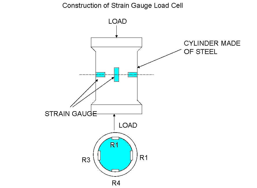
The main parts of the strain gauge load cell are as follows.
They are a cylinder made up of steel on which four identical strain gauge are mounted and out of four strain gauges, two of them (R1 and R4) are mounted along the direction of the applied load(vertical gauges).
The other two strain gauges (R2 and R3 Horizontal gauges) are mounted circumferentially at right angles to gauges R1 and R4.
Operation of strain gauge Load cell
Let’s study the operation in two cases
Case 1
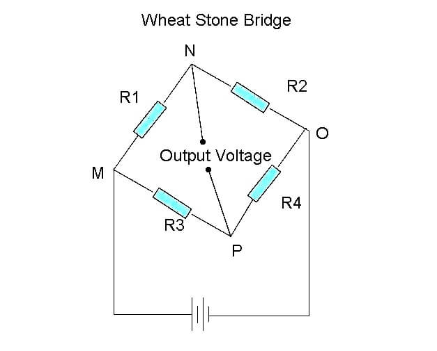
When there is no load (force) on the steel cylinder, all the four gauges will have the same resistance.
As the terminals N and P are at the same potential, the wheat stone bridge is balanced and hence the output voltage will be zero.
Case 2
Now the load (force) to be measured (say compression force) is applied on the steel cylinder. Due to this, the vertical gauges R1 and R4 will under go compression and hence there will be a decrease in resistance.
At the same time, the horizontal gauges R2 and R3 will under go tension and there will be an increase in resistance. Thus when strained, the resistance of the various gauges change.
Now the terminal N and P will be at different potential and the change in output voltage due to the applied load (force) becomes a measure of the applied load force when calibrated.
Uses of Strain Gauge Load Cell
- Strain gauge load cells are used when the load is not steady.
- Strain gauge load cells are used in vehicle weigh bridges, and tool force dynamometers.







in the 1st figure resistance R1 is repeated twice rather than R1 AND R2.