Programming a PLC includes defining and creating a lot of variables, there are many different types of variables that you can use in your PLC code. One of these types are the Static and Temp variables. They are used regularly in PLC programs.
In this article, we will discuss that is static and temp variables in PLC, what are the differences between them, and how to use them properly.
Contents:
- Simple program example.
- Simulation of the program
- Why the results are different?
- How to use this information?
- Conclusion.
Simple Program Example
To better understand these variables and how they work let’s start by creating a simple PLC program to help us understand what static and temp variables are.
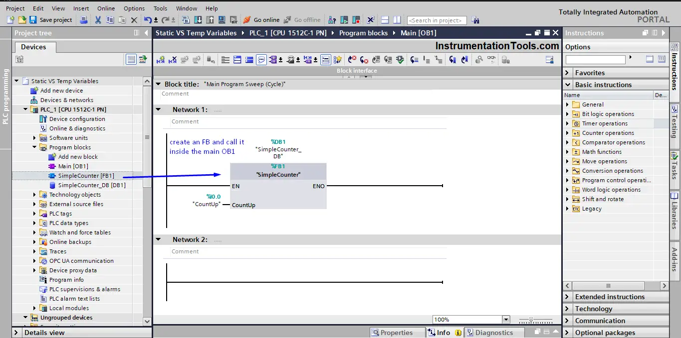
We will start by creating a function block FB and we will call this FB inside the main OB1. See picture 1.
Inside this FB we will create a simple logic where we use the ADD instruction to add a value of 1 to a temp variable #Count_Value_Temp and do the same instruction but with a static variable #Count_Value_Static. See picture 2.
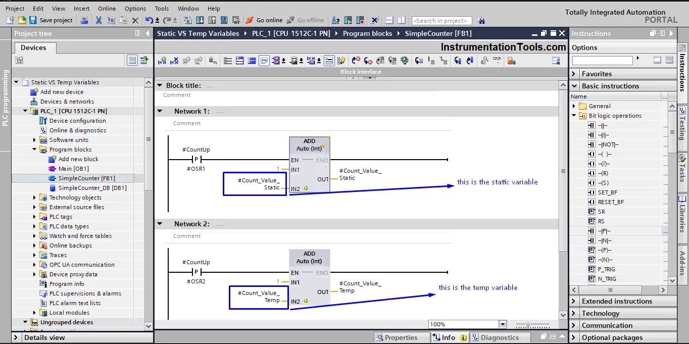
The logic as you can see is fairly simple, each time a rising edge is detected at input %I0.0 a value of 1 will be added to our two variables. So if I press and release the input %I0.0 three times, I should have a value of 3 inside the #Count_Value_Temp and #Count_Value_Static parameters.
Let’s run a PLC simulation and see what we will have. See the following animation for the simulation.
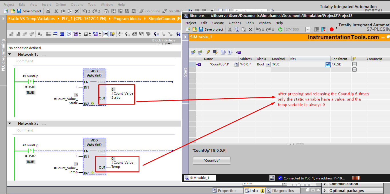
Did you notice what happened in the video? The #Count_Value_Temp was always with the value zero and did not change, even when the CountUp signal was pressed 6 times opposite to what we were expecting.
Whereas the #Count_Value_Static did change as we expected and the value after pressing the CountUp 6 times was also 6. See picture 3.
Why the Results are Different?
So, why the results were different? Even though it is the same exact logic.
This difference came from using different variables with the instruction result. When we used a static variable the result was as we expect it to be. But when we used a temp variable the result was not as expected.
In a nutshell, a Static variable will be stored permanently in your PLC memory whereas a Temp variable will be stored for a limited amount of time, usually, this time is the scan cycle time.
But, what difference does that make? See picture 4. To understand the difference.
As you can see from picture 4. The value of a temp variable will be reset to zero at the end of each scan cycle. So regardless of what calculation has been made to the temp variable within the scan cycle. This value will be reset to zero at the end of that scan cycle.
That means, even though we didn’t see it in the simulation video, the #Count_Value_Temp actually did change to 1 when the %I0.0 was present but at the end of the scan cycle, this 1 was reset to 0 that is why you didn’t see it change in the simulation.
On the other hand, a Static variable will be saved permanently inside the PLC memory. So at the end of each scan cycle, the result of whatever calculation was made to the Static variable will be saved. So the value of 1 will continue to be 1 after the scan cycle.
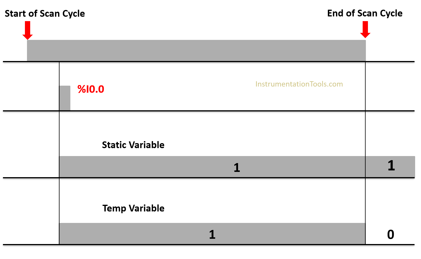
To understand this even more see picture 5. Which is a simulation of what happens each time the %I0.0 is pressed in a period of 6 scan cycles.
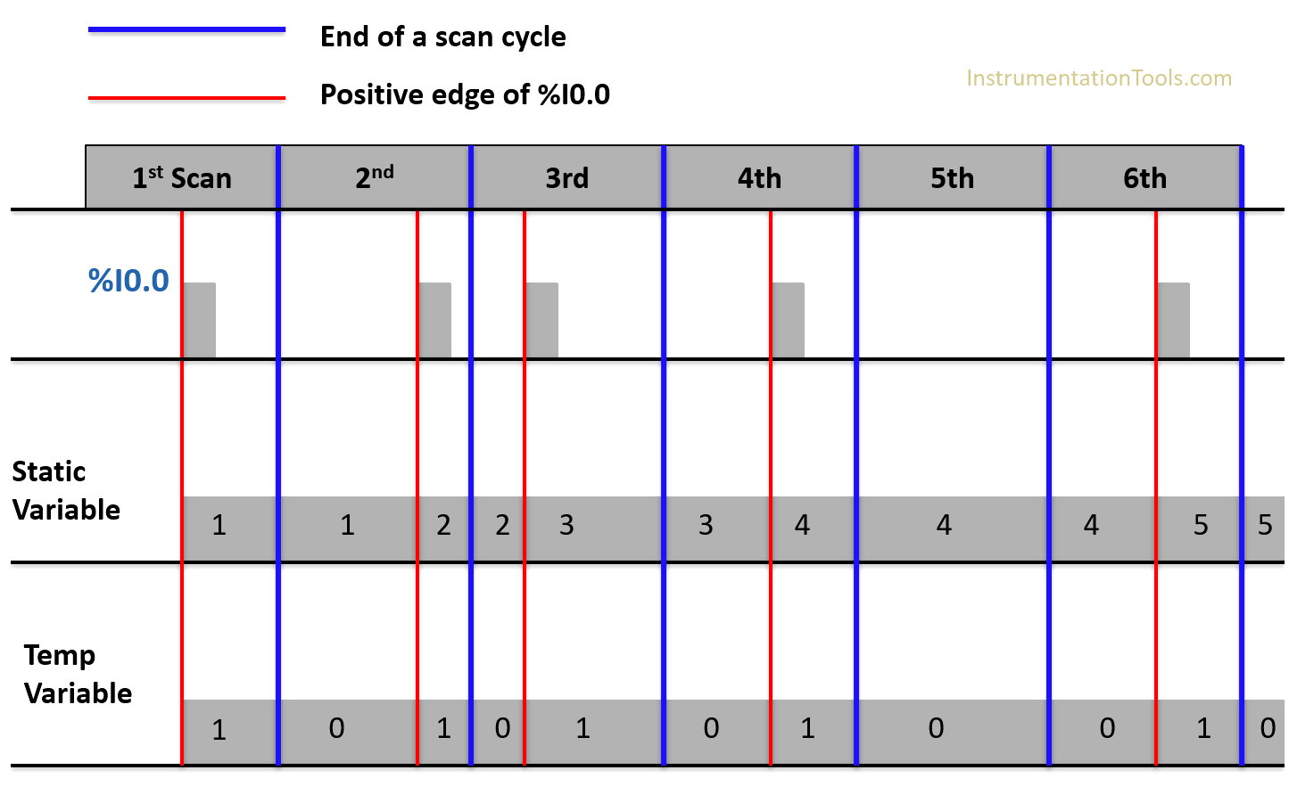
Static Variable
As you can see from the previous picture, each time a positive edge is triggered at %I0.0 the static variable value will be added to 1 then the new value will be stored in the Static variable again.
And that is why you see the value remains the same at the end of the scan cycle. After 6 scan cycles and 5 times the signal %I0.0 is present the value of #Count_Value_Static will be 5.
Temp variable
As you can see from the previous picture, each time a positive edge is triggered at %I0.0 the temp variable value will be 1, but then this value will be reset to zero again at the end of the scan cycle.
And that is why you see the value changes between 1 each time %I0.0 is true and zero each scan cycle end. After 6 scan cycles and 5 times the signal %I0.0 is present the value of #Count_Value_Temp will be 0.
How to use this information?
Now, what we discussed before doesn’t mean that using a temp variable is wrong or not recommended. Because temp variables are actually very important and using them has many benefits.
Of these benefits is the ability to reduce the size of used memory in the PLC. As the used memory for a temp variable will be reset to zero at the end of the scan cycle. Leaving this memory available to be used by other variables.
On the other hand, if you need to save your value, then using a static variable will be more suitable for your application. You just need to know what you want.
Downloads:
Conclusion
When programming a PLC, you usually use a lot of variables in your logic; of these variables, there are the Static and Temp variables. You need to understand and be aware of how each variable work inside your logic, so you can better use it for your needs.
Misusing the variable or failing to use it in a suitable way can lead to a lot of errors in your logic; some of these errors can’t even be detected by the compiler, so it will take more time and effort to debug.
If you liked this article, then please subscribe to our YouTube Channel for Instrumentation, Electrical, PLC, and SCADA video tutorials.
You can also follow us on Facebook and Twitter to receive daily updates.
Read Next:
- Safety PLC Coding Practices
- Industrial Automation Solution
- Automation Project Investment
- Choose HMI for Your Application
- 1oo2 Evaluation Safety Instruction