Split-range control is used when a single controller is employed to control two final-control elements (two valves for example).
In such a system, the controller struggle to keep one controlled variable at the set point using two manipulated variables.
Typically, split-range control is found in temperature control applications, but split-range control applications extend far beyond temperature control.
Split Range Control Working Principle
The concept of split-range control is easier to understand when illustrated using applications such as a temperature control.
In such an application, the process needs to be heated or cooled depending of the product temperature.
The below figure shows how the temperature transmitter, the controller, and the two control valves are connected for split-range control in a typical temperature control application.
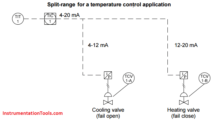
In the diagram above, the 0% to 100% range of the controller output is split in two between the two valves. If the controller output is between 0% and 50%, it is the cooling valve that operates.
This valve is fully open when the controller output is 0% and fully closed when the controller output is 50%. If the controller output is between 50% and 100%, it is the heating valve that is in operation.
At 50%, the heating valve starts to open and it is fully open at 100% of the controller output.
In a split-range control installation, there are different ways to connect the valves so that they operate on two different ranges.
In the example above, the current to pressure converters are used to split the controller output in two ranges.
The first converter responds to a current from 4 mA to 12 mA, while the other operates in a range from 12 mA to 20 mA.
When using this type of wiring, no special controller or configuration is required for split-range control.
Split Range Control Using Pneumatic Signals
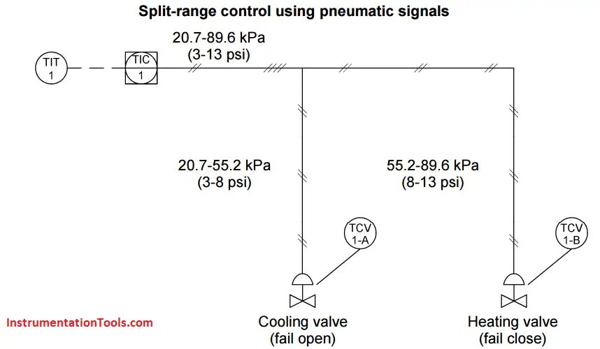
The below figure shows a setup that performs the same split-range control but, in this case, the signal from controller is a pneumatic signal. In such a setup, the two valves are mechanically different.
The spring/diaphragm actuators of the two valves are selected so that their ranges of operation are different.
The spring of the cooling valve is selected to allow the valve to open and close over a range of 20.7 kPa (3 psi) to 55.2 kPa (8 psi), while the heating valve closes and opens over a range of 55.2 kPa 8 psi to 89.6 kPa (13 psi).
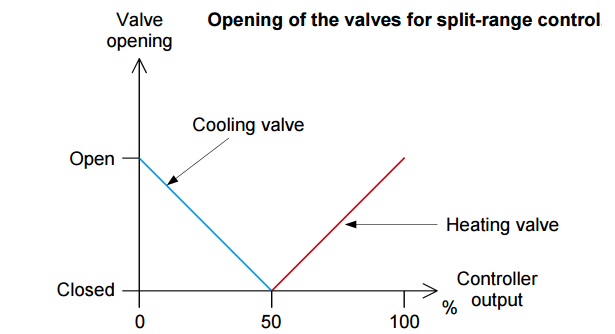
The opening and closing of the valves follow the same rules for both of the setups shown above.
The graph shows the relationship between the opening of the valves and the controller output.
Dead band for split range control
The examples above are some of the simplest setups for split-range control. Of course, a controller supporting split-range control may support more complex setups and correct some of the flaws inherent to split-range control.
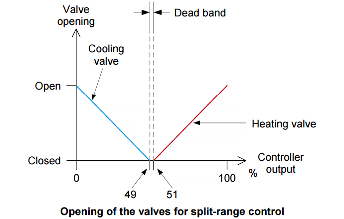
One problem that may arise with the setups detailed above is that the system may switch continuously between cooling and heating when the controller output is around 50%.
To avoid continuous oscillation between the cooling and heating modes, a dead band is usually added between the two ranges. A dead band can be added, for example, by setting a range of 0% to 49% for the cooling valve and a range of 51% to 100% for the heating valve.
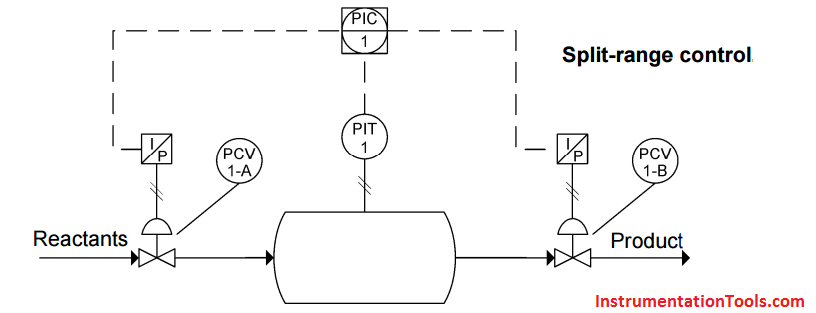
Using split-range to control the input and output of a reactor
The below figure shows another example of split-range control. In this example, chemical reactants come into a reactor via a first control valve that limits the input flow.
Another control valve limits the output flow of the reactor. To ensure a high-efficiency chemical reaction and a uniform product, the pressure inside the reactor must be kept above a given level.
A pressure transmitter reads the pressure in the reactor and a controller, connected for split-range control, changes its output to control the pressure inside the reactor.
If the pressure is too low, the controller opens the input valve. If the pressure is still low, the controller closes the output valve.
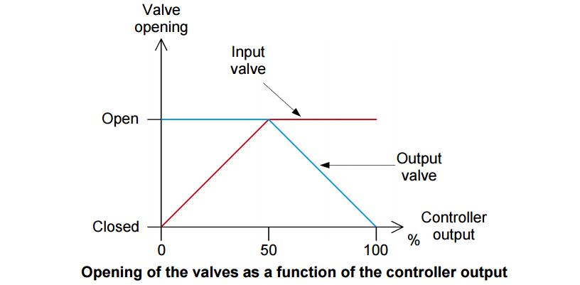
The below graph shows the opening of the control valves as a function of the controller output.
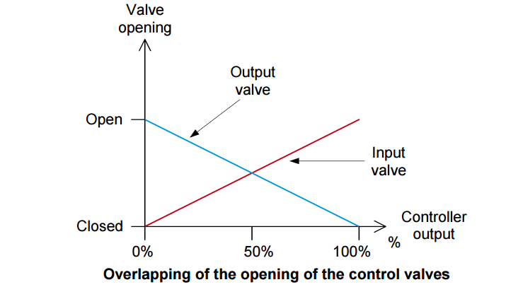
For this installation, the controller could also be configured so that the opening of the control valves overlap at 50% of the controller output, as shown in below Figure.
In this case, the output valve is fully open when the controller output is 0%, both valves are 50% open when the controller output is 50% and, finally, the input valve is fully open and the output valve is fully closed when the controller output is 100%.
Split-range control for a flare application
Gas flares are common in refinery and chemical plants. These devices are mainly used to burn the excess of flammable gas in a vessel and prevent an eventual explosion of due to over-pressure. When something goes wrong, the flare system is the insurance against disaster.
Many flare systems rely on split-range control for the evacuation of the gas.
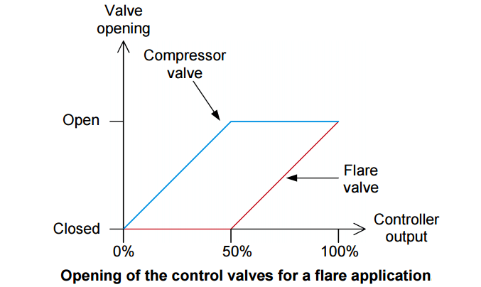
The below figure shows a typical split-range arrangement for a flare application.
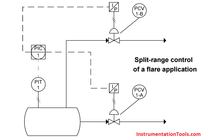
In a flare application, a fluid or a gas is processed in a vessel. The chemical reaction or the physical condition to which the fluid is exposed allows obtaining the desired product plus an (undesired) excess of flammable gas.
In the example above, it is a pressure transmitter that determines if the product is ready and if there is a gas excess.
The below figure shows the opening of the control valves as a function of the controller output for this flare application. If the pressure is low, the controller output is 0% and both valves are closed to allow pressure to build up in the vessel and the formation of the product.
As the pressure increases, the control valve allowing the product to exit the vessel and go to the gas compressor opens. This valve continues to open until the controller output reaches 50%.
At this point, the valve is fully open while the flare valve is still closed. If the pressure still increases, it indicates to the controller that there is an excess of gas that must be evacuated.
Thus, the controller increases its output and the flare valve starts to open to evacuate the gas and burn it. When the controller output reaches 100% both valves are fully open.


Machine monitoring system, how its works? And what type of problem generally arise and how it solve?
Noted. An article will be posted soon. Thanks
Centrifugal Compressor usually have such type of control,having one CV at Inlet and other at By-pass, in order to achieve constant pressure or flow requirements.
can we use single I to p to control both valve then how will those fail open and fail close of valve work, we have a common I TO P in site for temperature control valve both valve are air to close type.
How will fail action happen in both valve is in air to close with single I to P connection.
it is in split range control