Static electricity is a major cause of fires and explosions where flammable powders and liquids are stored and handled. The hazard of electrostatic spark ignition of a flammable vapor can be minimized by taking actions to limit the accumulation of electrostatic charges to safe values. Of primary importance is the proper bonding and grounding of equipment and containers.
In addition, charge accumulation must be limited, in many instances, by controlling the rate of charge generation and/or the rate of charge dissipation. Occasionally, such methods cannot be applied and the use of an inert gas in vapor spaces must be used.

Sources of Static Grounding
The most common sources of static electricity are processes using flammable powders and liquids. Static electricity is generated by materials flowing through pipes and in mixing, pouring, pumping, filtering or agitating. The rate of generation is influenced by conductivity, turbulence, the interface area between the materials and other surfaces, velocity and the presence of impurities.
Some specific areas where static electricity is generated include:
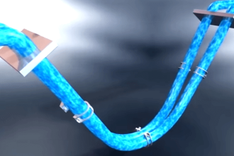
Piping Systems
In piping systems, the generation rate and the subsequent accumulation of static charges are a function of the materials, the flow rate, flow velocity, pipe diameter and pipe length.
Filling Operations
The turbulence experienced in filling operations caused by high flow rates, splashing or the freefalling of liquids or powder fines and the need to connect and disconnect hoses, valves and the like increases the charge accumulation and the chances of a hazardous charge.
Filtration
Filters, because of their large surface area, can generate as much as 200 times the electrostatic charge generated in the same piping system without filters.
Dispersing Operations
Dispersing operations can be particularly hazardous in view of the extremely high rate of charge generation when particulates are present. With poorly conductive materials, the charge accumulation can cause hazardous sparking in the mixer, such as to an exposed agitator bar or to a conductive fill pipe in a ball or pebble mill. High charge generation rates can also occur when materials are mixed, thinned, combined or agitated.
Methods of Static Control
In addition to being dependent on the charge generation rate, charge accumulation is a function of the resistance of the path by which charges dissipate. Within the material, the dissipation of static electricity is dependent on the material’s “conductivity.”
Some flammable liquids have a very low conductivity and tend to accumulate static charges. Toluene, an example of such a liquid, has a long history of causing industry fires. Lange’s Handbook lists conductivity data of some pure liquids.
Although the generation of static electricity cannot be eliminated, its rate of generation and accumulation can be reduced by the following procedures:
Piping Systems
The most effective method of reducing the accumulation of static charges in piping systems is through the proper pipe sizing to keep flow velocities low and to keep the flow as laminar as possible.
The typical maximum velocity in piping systems is 15 feet per second. Table 1 lists the flow rates for various pipe sizes for a velocity of 15 feet per second. Each user must determine the maximum velocity that can be safely allowed.

Table: 1
Filling Operations
Splash filling and free fall of flammable liquids should be eliminated to the maximum extent practical by lowering the fill velocities, by providing diverters to direct the discharge of material down the side of the grounded vessel being filled or by submerging fill pipes below the level in the vessel.
Submerging of fill pipes may not always be practical. In bulk filling operations, the velocity of the incoming liquid typically should not exceed 3 feet per second until the pipe outlet is covered. The velocity may then be increased to the 15 feet per second mentioned previously. Table 6-2 also lists the flow rates for various pipe sizes for the velocity of 3 feet per second.
Filtration
Experience has shown that the static electricity hazard may be controlled by installing filters far enough upstream of the discharge point to provide a 30 second relaxation time period prior to discharge. The relaxation time depends upon the conductivity, the liquid velocity and the type of filter. For example, the 30 second relaxation time may not be necessary with a highly conductive liquid.
Dispersing Operations
For dispersing operations of solids into liquids, the conductivity of the liquid should be raised, if necessary, to above 2000 conductivity units (C.U.), which is 2 x 10⁻⁵ micromho/cm, before particulates are added. If possible, polar solvents should be added before non-polar solvents or particulates are added. Polar solvents are more conductive than non-polar solvents. In some instances, proprietary anti-static agents, developed for use with fuels, can be used as additives to reduce the charge accumulation.
Typically, only a few parts per million of the additive are required. Tests should be conducted to ensure that the conductivity additive does not cause formulation problems. The additive may not be suitable for use in coatings for food containers. If the liquid conductivity cannot be raised to the recommended value, the vessel should be inerted (filled with an inert material).
For dispersing solids into solids, contact with the mixing vessel or agitator is the usual path to ground. Raising the humidity level in the mixer and/or providing a liquid conductive medium to dissipate the charge will help. If this is not possible, the vessel should be inerted. It should be noted that the static accumulation in liquids should be controlled by raising the ambient humidity.
Pebble mills present an additional hazard because the porcelain lining is an insulator that will prevent the flow of static charges from the liquid to ground, even if the mill is grounded. This hazard is best controlled by inerting the mill.
Nonconductive Plastic Containers and Stretch Film
The use of nonconductive plastic containers in potentially flammable locations may be an ignition hazard. Static charge accumulations on such containers, caused by the transfer of poorly conductive materials or by contact charging, cannot be dissipated by bonding and grounding.
Contact (“triboelectric”) charging of a nonconducting container in a low humidity environment creates a spark ignition hazard by inducing charges in materials in a container. These induced charges may cause sparking, for example, when the material is poured into a grounded safety can. Surprisingly, this hazard of charge induction is greatest when the material is conductive.
For example, experience in the coating industry suggests the following precautions:
Fiberboard Drums
No hazard of static accumulation except for metal rims which should be grounded during product transfer.
Kraft Paper Bags and Plastic – Lined Paper Bags
No hazard with paper bags. Plastic-lined paper bags are usually not hazardous, but the static electrification for each bag/contents combination should be measured.
All plastic bags and bags with removable plastic liners should be avoided unless measurements of electric field intensity at the bag surface during product transfer is less than 5 kV/cm (12.5 kV/inch).
Plastic Bottles and Nonconductive Drum Liners
Both of these items are subject to the hazard of charge induction as a result of electrification. Precautions must be taken to minimize contact charging or to neutralize contact charges before use. Removal of plastic bottles from plastic bags may cause contact charging.
Electric field intensities greater than 5 kV/cm (12.5 kV/inch) at the surface of the bottle or liner should be neutralized before a conductive flammable liquid is put into the bottle. It is also important to avoid charging a plastic bottle that even contains a small quantity of a conductive, flammable liquid.
Stretch Wrap
Stretch wrap must be removed from pallets in a nonflammable location. This material is usually highly charged and represents a serious hazard in flammable locations.
Semi-Bulk “Supersacks”
Electrostatic field intensity at the bag surface should be less than 5 kV/cm (12.5 kV/inch). Bags that contain metallic filaments must be grounded during product transfer.
Conductive Plastic Liners and Containers
Although most plastic materials are nonconductive, some conductive plastic liners and containers are commercially available. Conductive plastic materials must be grounded during product transfer in flammable locations.
Do you face any problems with static grounding? Share with us.
Reference: erico
Read Next:
- What is Electrical Grounding?
- Advantages of Grounding
- Turbine Protective Devices
- Single Phase Earth Return System
- Tips for Ground Loop Problems