This article will discuss an automatic street lighting system using XG-5000 PLC, which can adjust the lights’ on/off state based on light intensity (lumens) or the detection of vehicles and pedestrians. This PLC system aims to save electricity, improve road safety, and reduce operational costs.
Program Objective
System Steps:
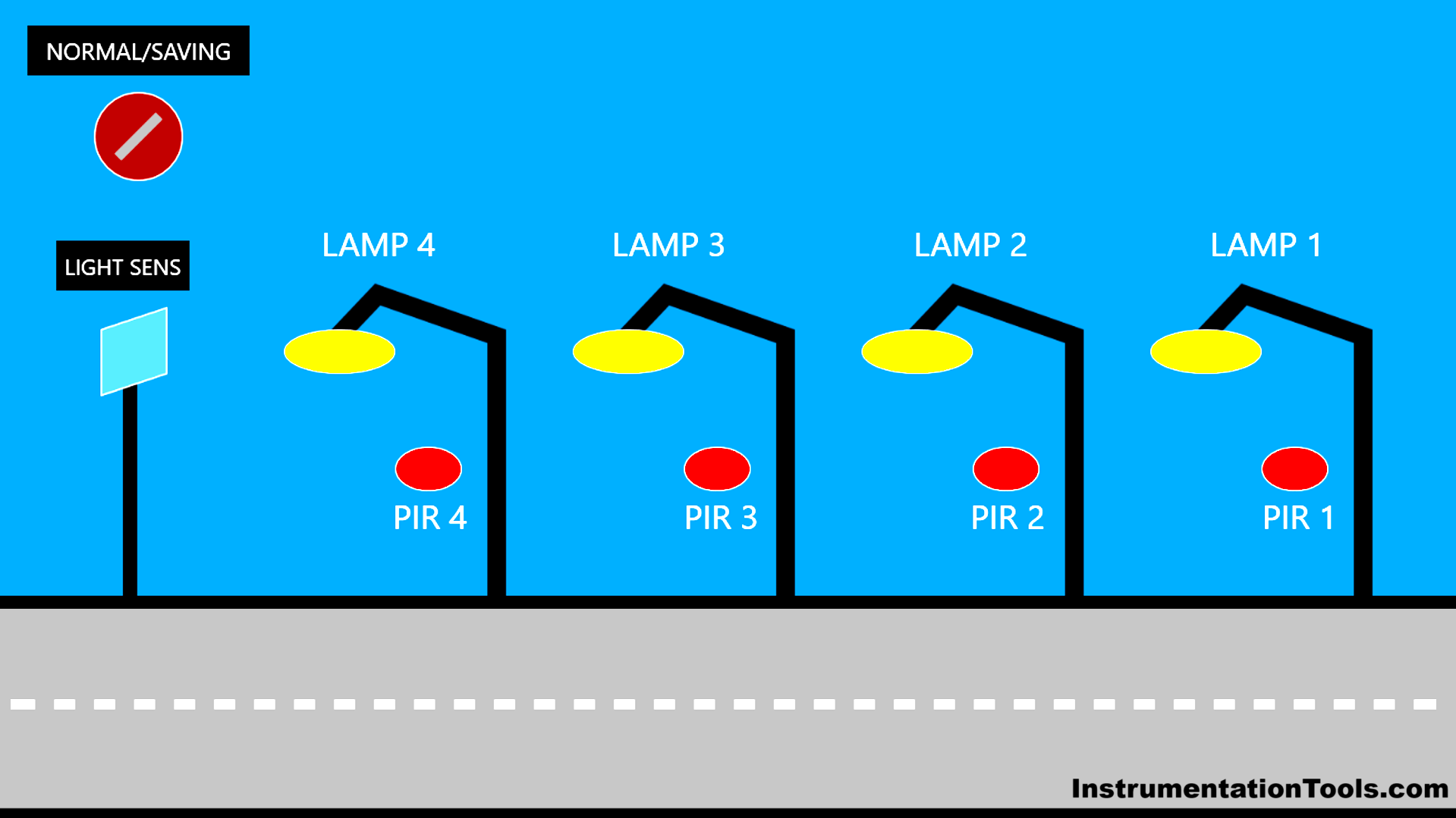
Mode selection can be done by adjusting the position of the selector switch to “Normal Mode” or “Saving Mode.”
Normal Mode:
- The light sensor will read the ambient light level every few seconds or minutes.
- The light level is expressed in lumens.
- When the lumen intensity is below 25, all four (4) lights turn On.
- When the lumen intensity is in the range of 26-50, two (2) lights turn On.
- When the lumen intensity is in the range of 51-100, only one (1) light turns On.
Saving Mode:
- In saving mode, light activation is based on motion detection using a PIR sensor to detect vehicles or pedestrians.
- The system consists of four (4) lights, and each light has its own motion/PIR sensor.
- The lights will only turn On when the sensor detects a moving object.
Smart Street Lighting

IO Mapping
| S.No. | Comment | Input (I) | Output (Q) | Memory Word | Memory Bit | Timer |
|---|---|---|---|---|---|---|
| 1 | PB_START | P0000 | ||||
| 2 | PB_STOP | P0001 | ||||
| 3 | NORMAL_OR_SAVING | P0002 | ||||
| 4 | PIR_SENS1 | P0003 | ||||
| 5 | PIR_SENS2 | P0004 | ||||
| 6 | PIR_SENS3 | P0005 | ||||
| 7 | PIR_SENS4 | P0006 | ||||
| 8 | LAMP1 | P0040 | ||||
| 9 | LAMP2 | P0041 | ||||
| 10 | LAMP3 | P0042 | ||||
| 11 | LAMP4 | P0043 | ||||
| 12 | LUMENS_PV | M010 | ||||
| 13 | SYSTEM_ON | M0000 | ||||
| 14 | IR1_PIR1 | M0001 | ||||
| 15 | IR1_PIR2 | M0002 | ||||
| 16 | IR1_PIR3 | M0003 | ||||
| 17 | IR1_PIR4 | M0004 | ||||
| 18 | IR_SAVING_1 | M0005 | ||||
| 19 | IR_SAVING_2 | M0006 | ||||
| 20 | IR_SAVING_3 | M0007 |
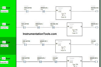
XG5000 PLC Programming
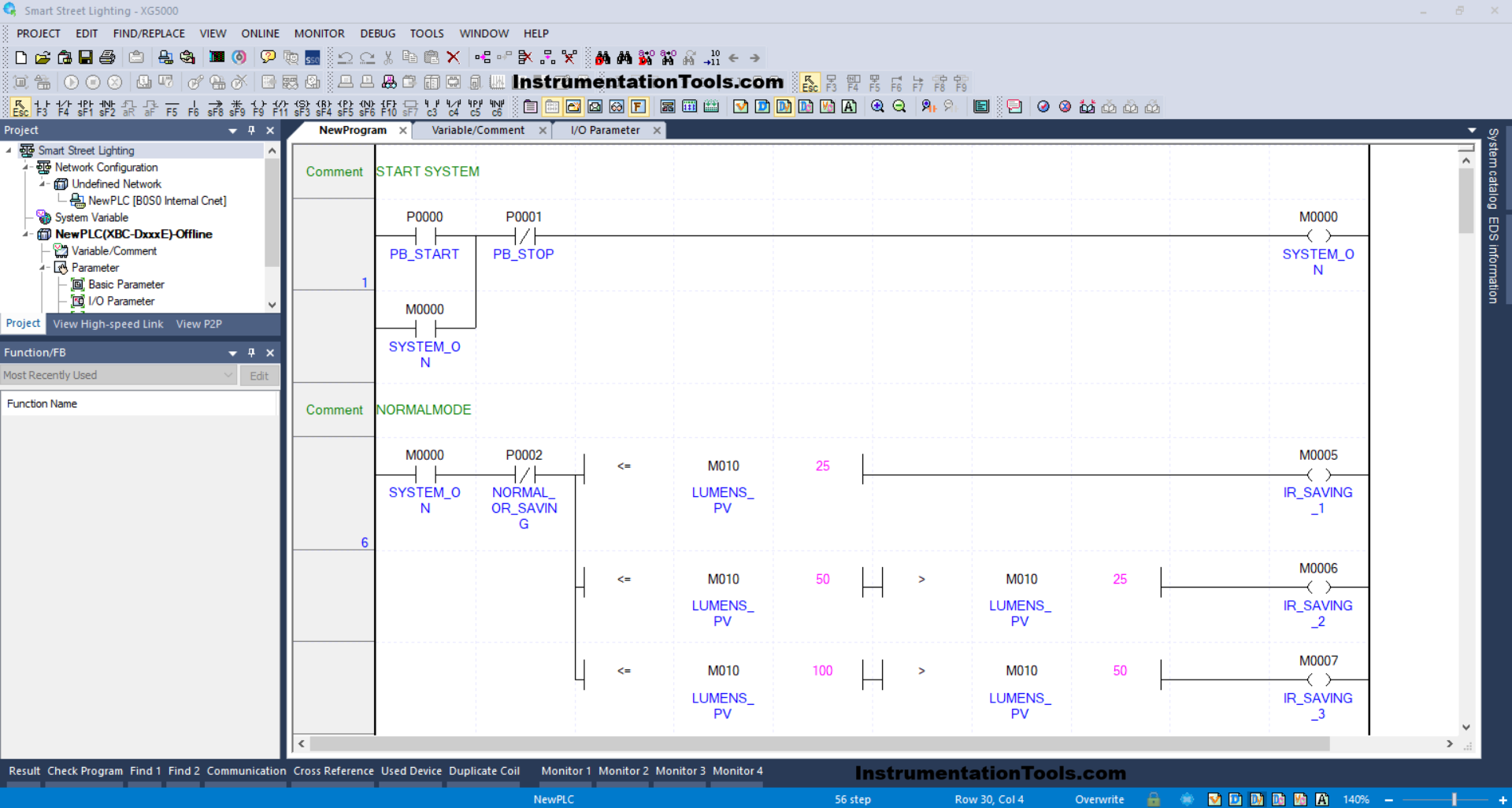
RUNG 1 (START SYSTEM)
In this rung, if the PB_START (P0000) button is Pressed, the memory bit SYSTEM_ON (M0000) will be in the HIGH state. Because it uses Latching, the memory bit SYSTEM_ON (M0000) will remain in the HIGH state even though the PB_START (P0000) button has been Released.
And when the PB_STOP (P0001) button is Pressed, the memory bit SYSTEM_ON (M0000) will return to the LOW state.
RUNG 6 (NORMAL MODE)
In this Rung, the memory bit IR_SAVING_1 (M0005) will be in the HIGH state if the NO contact of the memory bit SYSTEM_ON (M0000) is in the HIGH state and the value in the memory word LUMENS_PV (M010) is Less Than Or Equal To “25”.
The memory bit IR_SAVING_2 (M0006) will be in the HIGH state if the NO contact of the memory bit SYSTEM_ON (M0000) is in the HIGH state and the value in the memory word LUMENS_PV (M010) is Less Than Or Equal To “50” and Greater Than “25”.
The memory bit IR_SAVING_3 (M0007) will be in the HIGH state if the NO contact of the memory bit SYSTEM_ON (M0000) is in the HIGH state and the value in the memory word LUMENS_PV (M010) is Less Than Or Equal To “100” and Greater Than “50”.
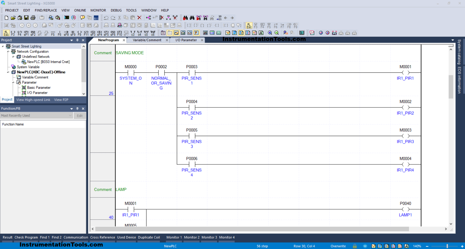
RUNG 25 (SAVING MODE)
In this Rung, when the NO contact of the memory bit SYSTEM_ON (M0000), NORMAL_OR_SAVING (P0002) selector switch, and PIR_SENS1 (P0003) sensor are in the HIGH state, then the memory bit IR1_PIR1 (M0001) will be in the HIGH state.
When the PIR_SENS2 (P0004) sensor is in the HIGH state, the memory bit IR1_PIR2 (M0002) will be in the HIGH state.
When the PIR_SENS3 (P0005) sensor is in the HIGH state, the memory bit IR1_PIR3 (M0003) will be in the HIGH state.
When the PIR_SENS4 (P0006) sensor is in the HIGH state, the memory bit IR1_PIR4 (M0004) will be in the HIGH state.
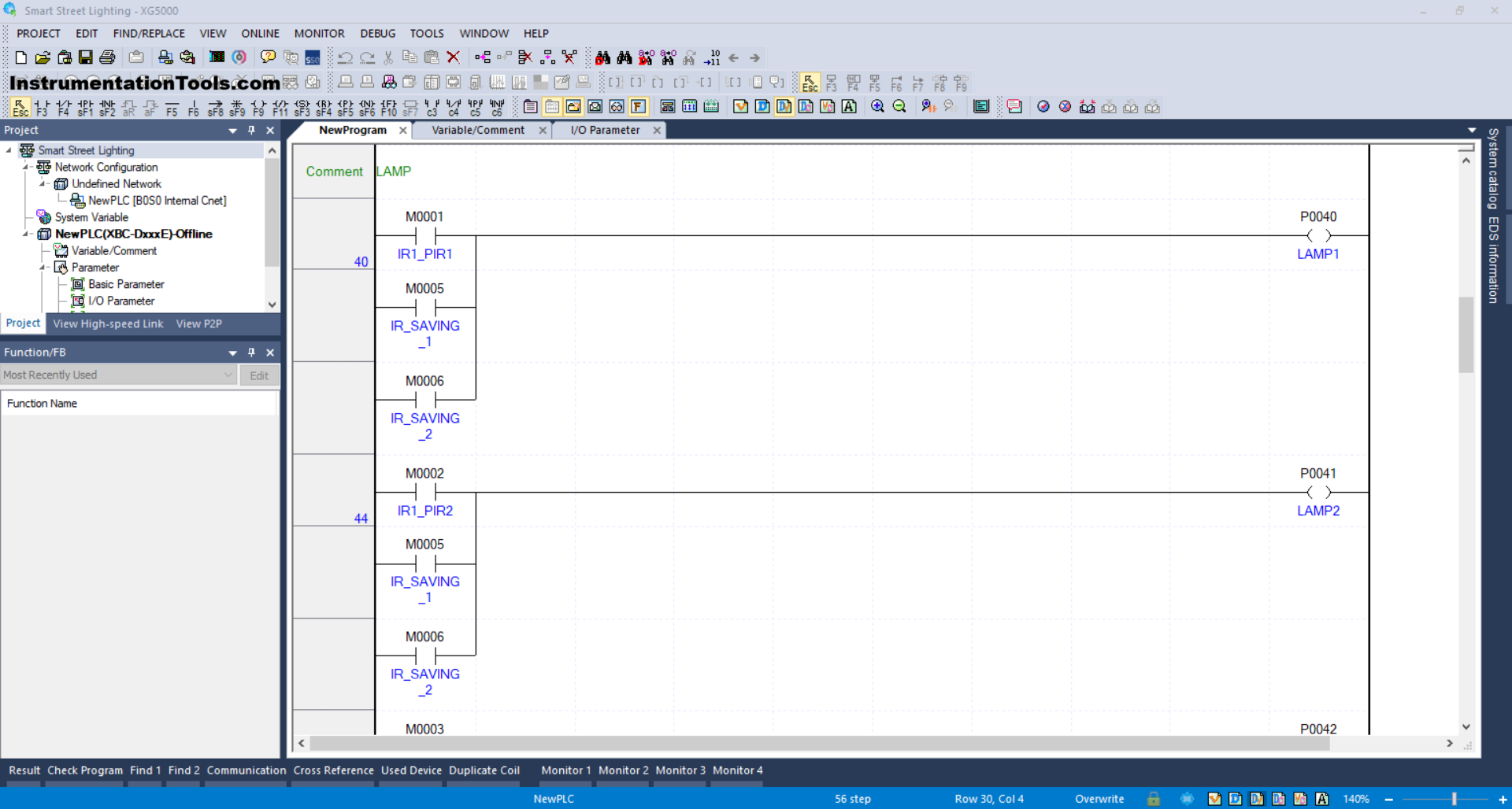
RUNG 40 (LAMP)
In this Rung, the LAMP1 (P0040) output will be ON if any of the NO contacts of the memory bits IR1_PIR1 (M0001), IR_SAVING_1(M0005), or IR_SAVING_2(M0006) is in the HIGH state.
RUNG 44
In this Rung, the LAMP2 (P0041) output will be ON if any of the NO contacts of the memory bits IR1_PIR2 (M0002), IR_SAVING_1 (M0005), or IR_SAVING_2 (M0006) is in the HIGH state.
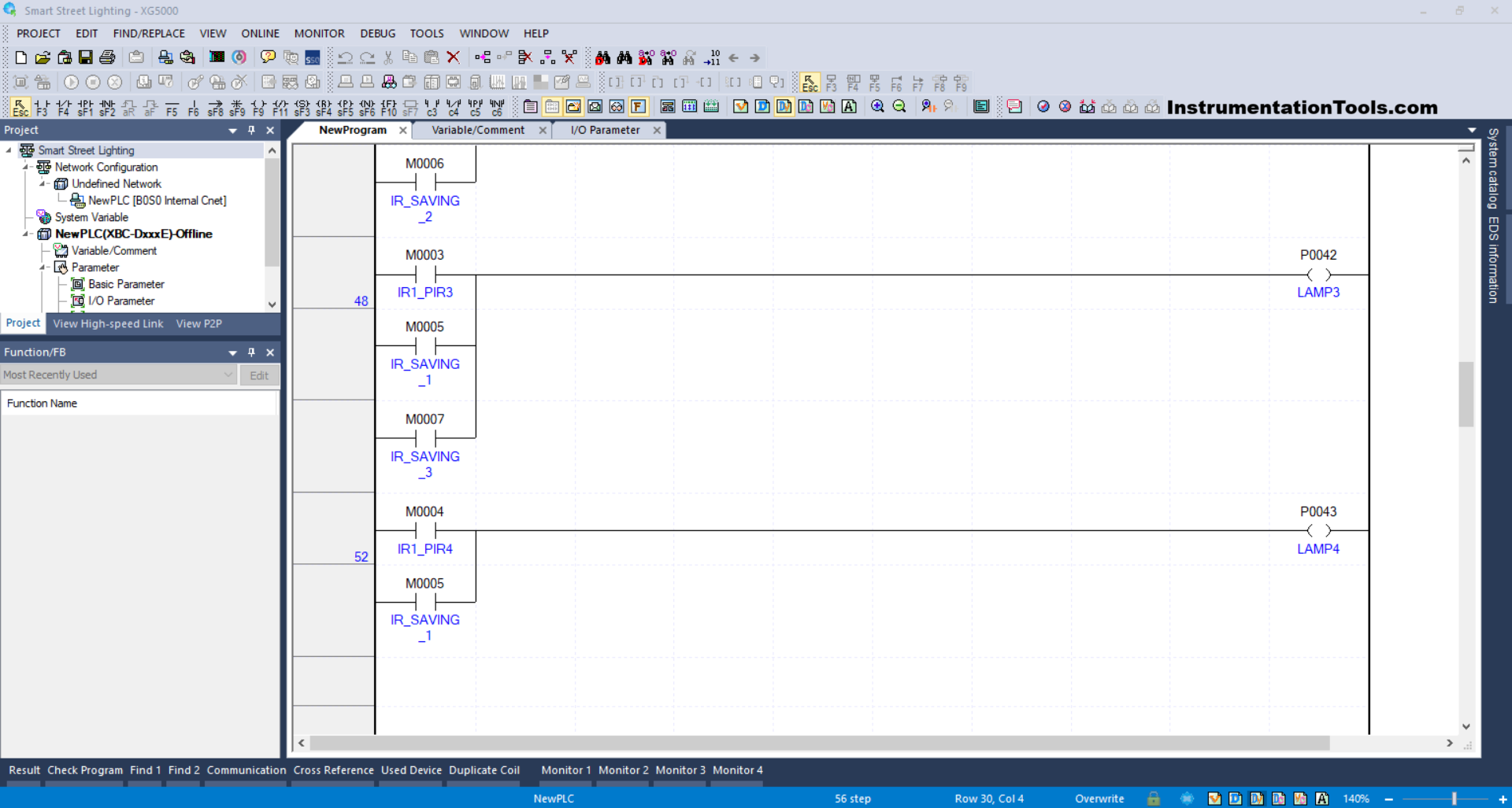
RUNG 48
In this Rung, the LAMP3 (P0042) output will be ON if any of the NO contacts of the memory bits IR1_PIR3 (M0003), IR_SAVING_1 (M0005), or IR_SAVING_3 (M0007) is in the HIGH state.
RUNG 52
In this Rung, the output LAMP4 (P0043) will be ON if the NO contact of the memory bit IR1_PIR4 (M0004) or IR_SAVING_1 (M0005) is in the HIGH state.
Read Next:
- Escalator Control Based on Passenger Load in PLC
- OB20 Time Delay Interrupt Organization Block
- PLC OB10 Time of Day Interrupt Organization Block
- Siemens Tia Optimized and Standard Data Block Access
- Difference between Motion Controller and PLC System