Inst ToolsInst ToolsInst Tools
  • Courses
  • Automation
    • PLC
    • Control System
    • Safety System
    • Communication
    • Fire & Gas System
  • Instrumentation
    • Design
    • Pressure
    • Temperature
    • Flow
    • Level
    • Vibration
    • Analyzer
    • Control Valve
    • Switch
    • Calibration
    • Erection & Commissioning
  • Interview
    • Instrumentation
    • Electrical
    • Electronics
    • Practical
  • Q&A
    • Instrumentation
    • Control System
    • Electrical
    • Electronics
    • Analog Electronics
    • Digital Electronics
    • Power Electronics
    • Microprocessor
  • Request
Search
  • Books
  • Software
  • Projects
  • Process
  • Tools
  • Basics
  • Formula
  • Power Plant
  • Root Cause Analysis
  • Electrical Basics
  • Animation
  • Standards
  • 4-20 mA Course
  • Siemens PLC Course
Reading: SIS Logic Solver
Share
Font ResizerAa
Inst ToolsInst Tools
Font ResizerAa
  • Courses
  • Design
  • PLC
  • Interview
  • Control System
Search
  • Courses
  • Automation
    • PLC
    • Control System
    • Safety System
    • Communication
    • Fire & Gas System
  • Instrumentation
    • Design
    • Pressure
    • Temperature
    • Flow
    • Level
    • Vibration
    • Analyzer
    • Control Valve
    • Switch
    • Calibration
    • Erection & Commissioning
  • Interview
    • Instrumentation
    • Electrical
    • Electronics
    • Practical
  • Q&A
    • Instrumentation
    • Control System
    • Electrical
    • Electronics
    • Analog Electronics
    • Digital Electronics
    • Power Electronics
    • Microprocessor
  • Request
Follow US
All rights reserved. Reproduction in whole or in part without written permission is prohibited.
Inst Tools > Blog > Safety Instrumented System (SIS) > SIS Logic Solver

SIS Logic Solver

Last updated: May 7, 2019 12:42 pm
Editorial Staff
Safety Instrumented System (SIS)
No Comments
Share
5 Min Read
SHARE

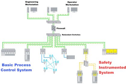
Control hardware for safety instrumented functions should be separate from the control hardware used to regulate the process, if only for the simple reason that the SIF exists to bring the process to a safe state in the event of any unsafe condition arising, including dangerous failure of the basic regulatory controls.

If a single piece of control hardware served the dual purposes of regulation and shutdown, a failure within that hardware resulting in loss of regulation (normal control) would not be protected because the safety function would be disabled by the same fault.

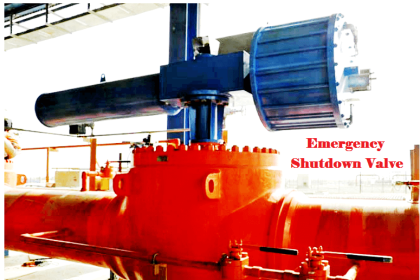
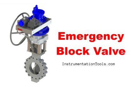
Safety controls are usually discrete with regard to their output signals. When a process needs to be shut down for safety reasons, the steps to implement the shutdown often take the form of opening and closing certain valves fully rather than partially.

This sort of all-or-nothing control action is most easily implemented in the form of discrete signals triggering solenoid valves or electric motor actuators.

SIS Logic Solvers

A digital controller specially designed for and tasked with the execution of safety instrumented functions is usually called a logic solver, or sometimes a safety PLC, in recognition of this discrete-output nature.

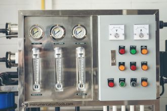
A photograph of a “safety PLC” used as an SIS in an oil refinery processing unit is shown here, the controller being a Siemens “Quadlog” model:

SIS Logic Solvers

Some logic solvers such as the Siemens Quadlog are adaptations of standard control systems (in the case of the Quadlog, its standard counterpart is called APACS).

In the United States, where Rockwell’s Allen-Bradley line of programmable logic controllers holds the dominant share of the PLC market, a version of the ControlLogix 5000 series called GuardLogix is manufactured specifically for safety system applications.

Not only are there differences in hardware between standard and safety controllers (e.g. redundant processors), but some of the programming instructions are unique to these safety-oriented controllers as well.

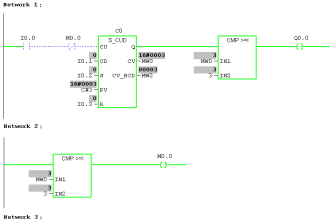
An example of a safety-specific programming instruction is the GuardLogix DCSRT instruction, which compares two redundant input channels for agreement before activating a “start” bit which may be used to start some equipment function such as an electric motor:

safety PLC programming

In this case, the DCSRT instruction looks for two discrete inputs to be in the correct complementary states (Channel A = 1 and Channel B = 0) before allowing a motor to start.

These states must not conflict for a time-span longer than 50 milliseconds, or else the DCSRT instruction will set a “Fault Present” (FP) bit.

As you can see, the form-C push button contacts are wired to two discrete inputs on the GuardLogix PLC, giving the PLC dual (complementary) indication of the switch status.

For specialized and highly critical applications, dedicated safety controllers exist which share no legacy with standard control platforms.

Triconex and ICS-Triplex are two such manufacturers, producing triple-modular redundant (TMR) control systems implementing 2oo3 voting at the hardware level, with redundant signal conditioning I/O circuits, redundant processors, and redundant communication channels between all components.

The nuclear power industry boasts a wide array of application-specific digital control systems, with triple (or greater!) component redundancy for extreme reliability.

An example of this is Toshiba’s TOSMAP system for boiling water nuclear power reactors, the digital controller and electro-hydraulic steam turbine valve actuator subsystem having a stated MTBF of over 1000 years!

44MTBF stands for Mean Time Between Failure, and represents the reliability of a large collection of components or systems.

For any large batch of identical components or systems constantly subjected to ordinary stresses, MTBF is the theoretical length of time it will take for 63.2% of them to fail based on ordinary failure rates within the lifetime of those components or systems.

Thus, MTBF may be thought of as the “time constant” (τ) for failure within a batch of identical components or systems.

Articles You May Like :

Instrumentation Cyber Security Glossary

What is Distributed Control Systems (DCS) ?

Safety Integrity Level (SIL)

Speed of Power Actuators

Difference Between SCADA and HMI

Don't Miss Our Updates
Be the first to get exclusive content straight to your email.
We promise not to spam you. You can unsubscribe at any time.
Invalid email address
You've successfully subscribed !

Continue Reading

Safety Instrumented Systems Online Exam
What is Safety Instrumented Functions ?
SIS Testing and Repair Deferral
SIS Verification & Validation – Safety Instrumented System
Understanding High Integrity Pressure Protection Systems (HIPPS)
ESDV : How it Works ?
Share This Article
Facebook Whatsapp Whatsapp LinkedIn Copy Link
Share
Leave a Comment

Leave a Reply Cancel reply

Your email address will not be published. Required fields are marked *

Stay Connected

128.3kFollowersLike
69.1kFollowersFollow
210kSubscribersSubscribe
38kFollowersFollow

Categories

Explore More

Functional Safety Questions & Answers
Transistor Failure Rate Calculation
SIS Maintenance – Safety Instrumented System
What is High Integrity Pressure Protection System?
Voting Logic in Safety Instrumented System (SIS)
What is Burner Management System (BMS)?
High Reliability of Safety Instrumented Systems
Safety Integrity Level (SIL)

Keep Learning

What is HIPPS System in Oil and Gas

What is HIPPS System in Oil and Gas?

failure rate of a component - 1

Failure rate and MTBF of Safety Instrumented Systems

Control Valve Failure Rate Calculation

Control Valve Failure Rate Calculation

Safety Control System

What is Safety Control System ?

BPCS Control System and ESD Safety System of Delta-V DCS

BPCS Control System and ESD Safety System of Delta-V DCS

Bathtub curve

Bathtub Curve

Proof Testing - Safety Instrumented System (SIS)

What is Proof Testing? – How to do a Proof Test? – Importance, Methods

Logic Solver in Safety PLC

What is a Logic Solver? – Safety PLC

Learn More

Safety Questions and Answers

Safety Questions and Answers

CO2 Stripper Old Differential Pressure Transmitter Stopped Working

CO2 Stripper Old Differential Pressure Transmitter Stopped Working

Clamp Meter

What is a Clamp Meter?

Current to percentage conversion

Convert current (4-20mA) to Percentage (0-100%)

AC Generator Operation

AC Generator Theory

Alarm prioritization

What is Alarm Prioritization? – Types of Alarms

Digital Electronics Multiple Choice Questions

Multiplexers Objective Questions – Part 1

Power Electronics Objective Questions

Power Electronics Filters Questions and Answers

Menu

  • About
  • Privacy Policy
  • Copyright

Quick Links

  • Learn PLC
  • Helping Hand
  • Part Time Job

YouTube Subscribe

Follow US
All rights reserved. Reproduction in whole or in part without written permission is prohibited.
Welcome Back!

Sign in to your account

Username or Email Address
Password

Lost your password?