Safety Instrumented System (SIS)

SIS Bypass and Impairment – Safety Instrumented System

Safety Instrumented System (SIS) Logics are built with safety interlocks considering multiple safe scenarios for protecting the equipment/plant. The functionality of such logics implemented either in the Basic Process Control System (BPCS) or Safety System (SIS) is very critical for the plant operations.

However, there may be a need to bypass an SIS or BPCS Independent Protection Layer (IPL) function for specific reasons such as startup, testing, or maintenance.

Again bypasses shall be counterchecked and removed for bringing back the equipment to operate in a safe manner. To manage this, there shall be a management system to ensure that a bypass is removed once the condition that required it has been satisfied. 
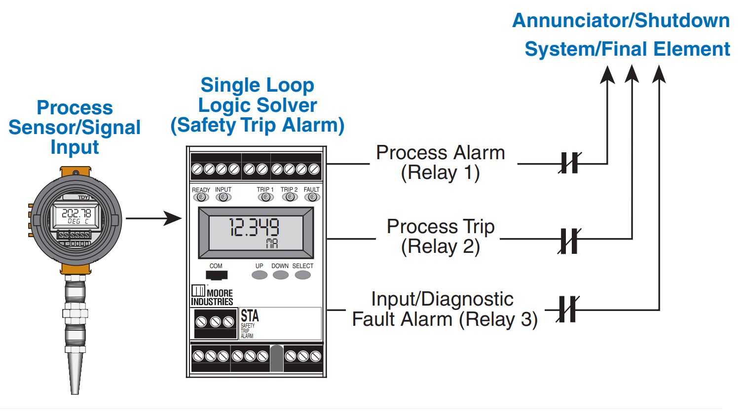
SIS Bypass and Impairment - Safety Instrumented System
Image Courtesy: Moore Industries

Bypass Rules

Written procedures shall exist for any hardware or software that permits bypass of an SIS function. 

For SIS, BPCS IPL safety functions, procedures to be made available to update, edit & Bypass (as and when required), and required System Access restrictions. The approach is applicable to all new installations, retrofits, and upgrade projects.

For BPCS protective function maximum time allowed for an instrument out of service should be minimized and be limited to 14 days.

Necessary Management of Change (MOC) policy ## must be followed so that safety will be assured by other technical or administrative controls and shall consider the availability/bypass condition of other protection layers for affected scenarios.

## Terminology may vary depending on the plant.

Bypass Requirements & Restrictions

  • By-pass switches must be protected by a key lock or password to prevent unauthorized use.
  • The indication must be provided that the SIS is bypassed by the alarm in DCS / Annunciator panel and/or develop the procedure.
  • Where a by-pass is required it should be installed such that alarms and manual shutdown facilities are not disabled.
  • Proper care to be taken for Bypassed instruments, valves also to be tested as part of SIS validation (when required).
  • Operators must be trained on the operation of the by-pass and requirements when it is to be used.
  • SIS design must minimize the need to impair the SIS while the unit is running.
  • Operation and maintenance procedures must be developed which provide the actions and constraints necessary to prevent or mitigate the hazard while the SIS is impaired.

Physical Hardware Restrictions

  1. Bypass valves installed around SIS “Final elements” must be secured in the “safe” position (typically, this is the “closed” position) with mechanical locks or car seals.
  2. A management system must include:
    • Control and access to lock keys or a half-yearly audit procedure for ensuring the integrity of seals.
  3. In-service operation of a bypass valve requires a written procedure which includes:
    • Approval by the relevant Business Head and the Process Safety Leader.
    • Actions that are necessary to prevent an unsafe state
    • Must ensure that the time the bypass valve is actually used is minimized
    • An inspection of the block valve to ensure that it is returned to the secured “safe” position.

Physical Software Restrictions

As part of the software, it requires access restrictions for operating bypasses around SIS components. However the implementation of “access restriction” is more stringent and requires “physical” restriction:

It is recommended that the bypassing must be “annunciated” visually or audibly.

Safety System Impairment

To protect against inadvertent bypassing of the protective function: software, hardware, and/or written procedures to be used so that the act of bypassing is annunciated and access-restricted – Implementation of the Safety System Impairment Standard is recommended. 

If “written procedures” are chosen as the method of preventing inadvertent bypassing, implementation of the practices to meet the intent of this requirement. 

Background

  • Need the ability to test Safety Instrumented System (SIS) when the plant is in operation.
    • Plant owners finalize Impairment requirements so that temporary safety system outages, impairments, and bypasses are always managed properly.

Brief Examples of SIS Impairment

What does it mean to “impair” a safety system?

Here are a few examples….

  1. If a Safety Function requires a valve in a steam/gas line to close when activated, the scenario may not be prevented if a bypass valve is open around the SIS final element.
  2. If a Safety Function requires a cooling water valve to open, the upstream block valve is closed, the scenario may not be prevented.
  3. Similarly, the SIS function may not be functional if software logic bypasses and closure of block valves in sensor lines.
  4. For instrument root valves: If the valve is clearly visible as an instrument root valve, SSI is not needed and the valve does not need to be locked open or tagged. This is because plant operations will not be using this valve to operate the plant. Since the instrument will have a Safety Instrument identification tag, this should be sufficient to alert maintenance personnel that the root valve will disable an SIS. However, if the root valve is located remotely from the instrument, it may not be obvious to operations that this is a maintenance valve. In this case, the SSI process should apply.
You've successfully subscribed !
Share

Recent Articles

  • PLC Tutorials

PLC Ladder Logic Design: Control 3 Motors with Toggle Switch

PLC ladder logic design to control 3 motors with toggle switch and explain the program…

3 weeks ago
  • PLC Tutorials

VFD Simulator Download – Free Yaskawa V1000 Software

VFD simulator download: Master the online tool from the Yaskawa V1000 & programming software for…

3 days ago
  • PLC Tutorials

Conveyor Sorting Machine PLC Program with Calculation Function

The conveyor sorting machine is widely used in the packing industries using the PLC program…

6 days ago
  • PLC Tutorials

Example of Flip-Flop PLC Program for Lamps Application

Learn the example of flip-flop PLC program for lamps application using the ladder logic to…

6 days ago
  • PLC Tutorials

STAR DELTA Programming using PLC Controller

In this article, you will learn the STAR DELTA programming using PLC controller to start…

7 days ago
  • Instrumentation Design

Single and Three Phase Immersion Electrical Heaters Wiring Circuits

Lube oil consoles of rotary equipment packages in industrial process plants are usually equipped with…

4 days ago