Inst ToolsInst ToolsInst Tools
  • Courses
  • Automation
    • PLC
    • Control System
    • Safety System
    • Communication
    • Fire & Gas System
  • Instrumentation
    • Design
    • Pressure
    • Temperature
    • Flow
    • Level
    • Vibration
    • Analyzer
    • Control Valve
    • Switch
    • Calibration
    • Erection & Commissioning
  • Interview
    • Instrumentation
    • Electrical
    • Electronics
    • Practical
  • Q&A
    • Instrumentation
    • Control System
    • Electrical
    • Electronics
    • Analog Electronics
    • Digital Electronics
    • Power Electronics
    • Microprocessor
Search
  • Books
  • Software
  • Projects
  • Process
  • Tools
  • Basics
  • Formula
  • Power Plant
  • Root Cause Analysis
  • Electrical Basics
  • Animation
  • Standards
  • 4-20 mA Course
  • Siemens PLC Course
Reading: Single Element Drum Level Control System
Share
Notification Show More
Font ResizerAa
Inst ToolsInst Tools
Font ResizerAa
  • Courses
  • Design
  • PLC
  • Interview
  • Control System
Search
  • Courses
  • Automation
    • PLC
    • Control System
    • Safety System
    • Communication
    • Fire & Gas System
  • Instrumentation
    • Design
    • Pressure
    • Temperature
    • Flow
    • Level
    • Vibration
    • Analyzer
    • Control Valve
    • Switch
    • Calibration
    • Erection & Commissioning
  • Interview
    • Instrumentation
    • Electrical
    • Electronics
    • Practical
  • Q&A
    • Instrumentation
    • Control System
    • Electrical
    • Electronics
    • Analog Electronics
    • Digital Electronics
    • Power Electronics
    • Microprocessor
Follow US
All rights reserved. Reproduction in whole or in part without written permission is prohibited.
Inst Tools > Blog > Control Systems > Single Element Drum Level Control System

Single Element Drum Level Control System

Last updated: April 17, 2019 4:49 pm
Editorial Staff
Control Systems
2 Comments
Share
2 Min Read
SHARE

The Below Figure depicts the control scheme for single-element drum level control. In this configuration, only the water level in the drum is being measured (hence the term ” single element” ) . LT- 1 is an electronic differential pressure transmitter with a high static pressure range.

The high side of the transmitter is connected to the bottom of the drum. Because of the drum’s static pressure, the low side of the transmitter is connected to the top of the drum above the water/steam interface. This provides a reference for the transmitter by cancelling the static pressure effect and allowing only the water hydrostatic head to be measured.

Single-element drum level control system

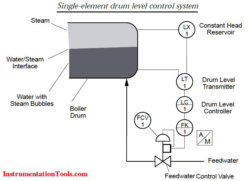
A constant head reservoir is required to maintain a consistent head in the reference leg of the transmitter. This is often referred to as a ”wet leg” The output of the electronic DP transmitter is the process Input for the  Controller, (LC-1), and the output is then compared to a drum level set-point. Any discrepancy between set-point and drum level causes an output from the controller in compensation.

Because controller action is reverse, as the drum level Increases, a resultant output signal will decrease to close the feedwater control valve. The output of the Controller is fed to the feedwater control valve (FCV-1). If the feedwater valve is pneumatic, an lP (current-to-pressure) converter is required to change the Controller current output to accommodate the pneumatic valve.

Note that the response from the controller to the feedwater control valve is reactive; i.e. feedwater is added only in response to a drop in drum level. This type of control is acceptable if steam load changes are not dramatic because the controller can respond well to steady demands. In applications where steam load changes become frequent and unpredictable, a reactive strategy is better suited. This type of system requires more field devices for input.

Source : ABB

Don't Miss Our Updates
Be the first to get exclusive content straight to your email.
We promise not to spam you. You can unsubscribe at any time.
Invalid email address
You've successfully subscribed !

Continue Reading

Self-regulating Processes – Liquid Flow Control
Basics of Loop Powered Devices
Alarm and Trip Systems
Types of Cables used in Industrial Automation
Open Loop and Closed Loop Animation
Functional Design Specifications for DCS and SIS Projects – FDS Document
Share This Article
Facebook Whatsapp Whatsapp LinkedIn Copy Link
Share
2 Comments
  • M R RAVI CHANDRAN says:
    December 29, 2016 at 1:25 pm

    SIR, WHAT IS MAIN REASON THE DRUM LEVEL LT DP TYPE IS REVERSE MOUNTED, LP AT LOW SIDE AND HP AT HIGH SIDE?, PLEASE CLARIFY

    Reply
  • chuangbing chen says:
    June 8, 2021 at 9:08 pm

    In applications where steam load changes become frequent and unpredictable, a reactive strategy is better suited. This type of system requires more field devices for input.

    There is a typo in this statement. Instead of reactive, it should be active.

    Reply

Leave a Reply Cancel reply

Your email address will not be published. Required fields are marked *

Stay Connected

128.3kFollowersLike
69.1kFollowersFollow
210kSubscribersSubscribe
38kFollowersFollow

Categories

Explore More

Boiler Three Element Controller Philosophy
Types of Noise in Electronics
MODBUS ASCII Communication Protocol Explained
Cascade Control Principle
How to Create a Project in LabVIEW?
What is Advanced Process Control (APC)?
What is Loop Checking?
Electrical and Instrumentation – Automation Pre-engineering Documents

Keep Learning

Open Platform Communication (OPC)

Open Platform Communication (OPC)

PID Controller Tunning Manually

PID Controller Parameters Tuning Manually

Analog inputs in library

Design Process Graphics in Factory Talk View Studio with an Analog Input

Industrial Automation and Control Systems (IACS)

Industrial Automation and Control Systems (IACS)

Advantages of Redundant System

Redundant Automation Systems – Need and Advantages

Process Alarms Types

Process Switches and Alarms

Boiler Drum Level Control Systems

Boiler Drum Level Control Systems

Discrete control system block diagram

Process Control Instrumentation

Learn More

Calculate Hydraulic Pressure of a Drum

Calculate Hydraulic Pressure of a Process Vessel

Open-Tank-DP-Level-Transmitter-with-Zero-Suppression-Calibration

DP Level Transmitter with Zero Suppression Calibration

Pulverizer Electrical Problem Solved

Pulverizer Electrical Problem Solved

Rupture disks

Rupture disks

How to Prevent Ground Loops in Analog Circuits?

How to Prevent Ground Loops in Analog Circuits?

CNC Custom Machining

What is Custom Machining in CNC? Why Should You Choose It?

Flow Meter Calibration Procedure

Flow Meter Calibration

Capacitance Pressure Sensor Principle

Electronic Pressure Sensors Principle

Menu

  • About
  • Privacy Policy
  • Copyright

Quick Links

  • Learn PLC
  • Helping Hand
  • Part Time Job

YouTube Subscribe

Follow US
All rights reserved. Reproduction in whole or in part without written permission is prohibited.
Welcome Back!

Sign in to your account

Username or Email Address
Password

Lost your password?