Let’s study the working shift and rotate instructions and its function in Siemens PLC programming with example ladder logic.
Shift and Rotate Instructions in PLC
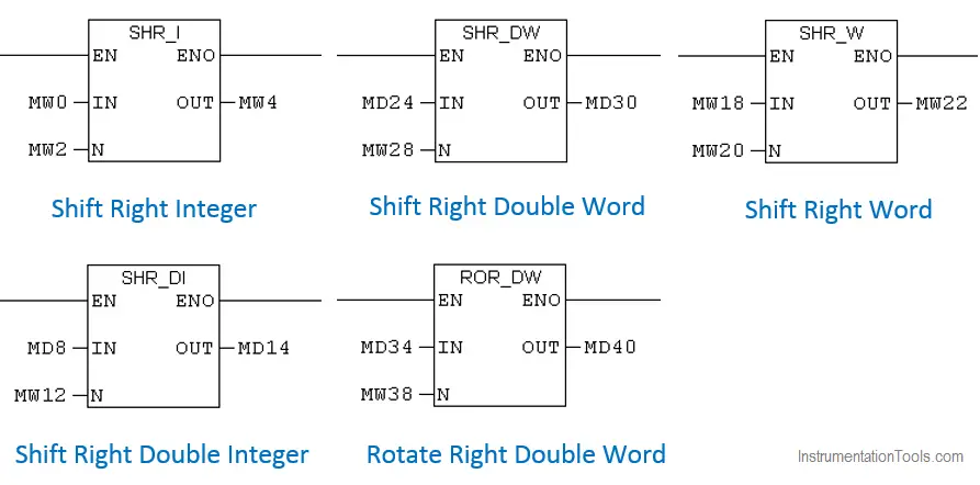
Block Description
Shift Right Integer:
Shift Right Integer instruction is used to shift bits 0 to 15 of input IN bit by bit to the right. The input N specifies the number of bits by which to shift.
After shifting, the bit position shifted in from the left to fill vacated bit position are filled with 0 if 15th bit (Sign bit) of input data is 0 or 1 id 15th bit (Sign bit) of input is 1.
Example 1:
Input IN: 1010 0110 1000 1000
N: 2
OUT: 1110 1001 1010 0010
Example 2:
Input IN :0011 0001 0001 1100
N:2
Output OUT : -0000 1100 0100 0111
Shift Right Double Integer:
Shift Right Double Integer instruction is used to shift bits 0 to 31 of input IN bit by bit to the right. The input N specifies the number of bits by which to shift.
After shifting, the bit position shifted in from the left to fill vacated bit position are filled with 0 if 15th bit (Sign bit) of input data is 0 or 1 id 15th bit (Sign bit) of input is 1.
Example 1:
Input IN: 0001 0111 1010 0111 1110 0011 1010 0101
N: 3
OUT: 0000 0010 1111 0100 1111 1100 0111 0100
Example 2:
Input IN :1011 1111 1111 0100 1110 0011 1010 0101
N:3
Output OUT : -1111 0111 1111 1110 1001 1100 0111 0100
Shift right Word:
Shift right Word instruction is used to shift bits 0 to 15 of input IN bit by bit to the right. The input N specifies the number of bits by which to shift.
After shifting, the bit position shifted in from the left to fill vacated bit position are filled with 0.
Example 1:
Input IN: 0011 0110 1100 0110
N: 2
OUT: 0000 1101 1011 0001
Example 2:
Input IN: 1111 0110 1100 1111
N: 2
Output OUT: -0011 1101 1011 0011
Shift Right double Word:
Shift Right double Word instruction is used to shift bits 0 to 31 of input IN bit by bit to the right. The input N specifies the number of bits by which to shift. After shifting, the bit positions shifted in from the left to fill vacated bit position are filled with 0.
Example 1:
Input IN: 0011 0110 1110 0011 1000 0110 0111 0111
N: 3
OUT: 0000 0110 1101 1100 0111 0000 1100 1110
Example 2:
Input IN : 1111 0110 1110 0011 1000 0110 0111 0111
N:3
Output OUT: -0001 1110 1101 1100 0111 0000 1100 1110
Read: Data Inside PLC
Rotate Right Double Word:
Rotate Right Double Word instruction is used to rotate the entire content of input IN bit by bit to the right. Input N specifies the number of bits by which to rotate.
The bit position shifted in from the left is assigned the logic states of the bits which were rotated out to the right.
Example 1:
Input IN : 1100 0110 0111 0011 0101 0101 1010 1100
N: 2
Output OUT: 0011 0001 1001 1100 1101 0101 0110 1011
Ladder Logic
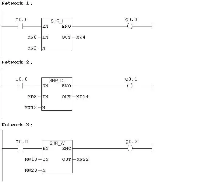
Network 1:
Input I0.0 is pressed, SHR_I instruction reads the value in MW0, shifting 2 bit right and result the output to MW4. Q0.0 enables as long as I0.0 enables.
Network 2:
Input I0.0 is pressed, SHR_DI instruction read the value in MD8, Shifting 3 bit right and result the output to MW14. Q0.1 enables as long as I0.0 enables.
Network 3:
Input I0.0 is pressed, SHR_W instruction reads the value in MW18, shifting 2 bit towards rights and result the output to MW22. Q0.2 enables as long as I0.0 enables.
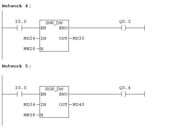
Network 4:
Input I0.0 is pressed, SHR_DW instruction reads the value in, Shifting 3 bit towards the right and result the output to MD30. Q0.3 enables as long as I0.0 enables.
Network 5 :
Input I0.0 is pressed, ROR_DW instruction reads the value in MD34, rotate the bits towards and result the output to MD40. Q0.4 enables as long as I0.0 enables.
Variable Table:
Variable is used to view the inputs and outputs in different formats.
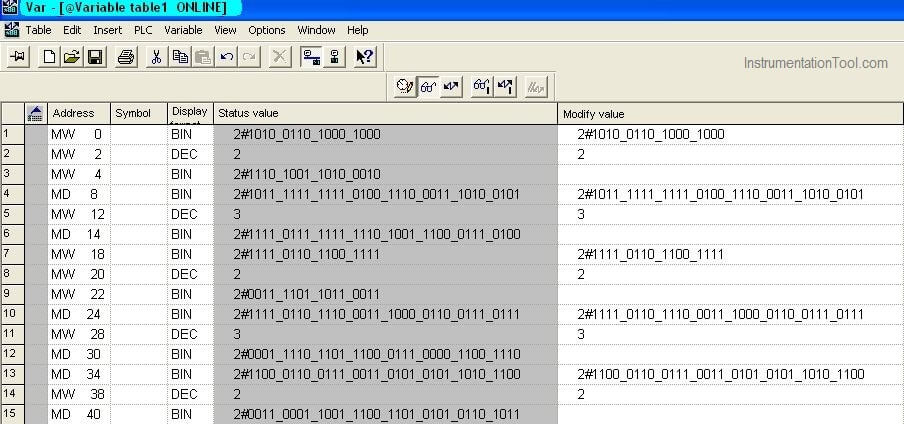
In Siemens, MW is the address used for integer data, MD is the address used for double integer data.
Status Value in Variable table is used to see the input and output values.
Modify the value in the variable table is used to give input data.
Author: Hema Sundaresan
If you liked this article, then please subscribe to our YouTube Channel for PLC and SCADA video tutorials.
You can also follow us on Facebook and Twitter to receive daily updates.
Read Next:
- Bitwise Logical Operations
- PLC Packaging System
- Memory Instructions in PLC
- Siemens PLC programming
- Pulse Timer Instruction in PLC





Dear team,
Thank you so much for valuable information , in the simplest way possible.
great job.