Inst ToolsInst ToolsInst Tools
  • Courses
  • Automation
    • PLC
    • Control System
    • Safety System
    • Communication
    • Fire & Gas System
  • Instrumentation
    • Design
    • Pressure
    • Temperature
    • Flow
    • Level
    • Vibration
    • Analyzer
    • Control Valve
    • Switch
    • Calibration
    • Erection & Commissioning
  • Interview
    • Instrumentation
    • Electrical
    • Electronics
    • Practical
  • Q&A
    • Instrumentation
    • Control System
    • Electrical
    • Electronics
    • Analog Electronics
    • Digital Electronics
    • Power Electronics
    • Microprocessor
  • Request
Search
  • Books
  • Software
  • Projects
  • Process
  • Tools
  • Basics
  • Formula
  • Power Plant
  • Root Cause Analysis
  • Electrical Basics
  • Animation
  • Standards
  • 4-20 mA Course
  • Siemens PLC Course
Reading: Sheets, Tags, Elements in Functional Block Diagram of Studio 5000
Share
Font ResizerAa
Inst ToolsInst Tools
Font ResizerAa
  • Courses
  • Design
  • PLC
  • Interview
  • Control System
Search
  • Courses
  • Automation
    • PLC
    • Control System
    • Safety System
    • Communication
    • Fire & Gas System
  • Instrumentation
    • Design
    • Pressure
    • Temperature
    • Flow
    • Level
    • Vibration
    • Analyzer
    • Control Valve
    • Switch
    • Calibration
    • Erection & Commissioning
  • Interview
    • Instrumentation
    • Electrical
    • Electronics
    • Practical
  • Q&A
    • Instrumentation
    • Control System
    • Electrical
    • Electronics
    • Analog Electronics
    • Digital Electronics
    • Power Electronics
    • Microprocessor
  • Request
Follow US
All rights reserved. Reproduction in whole or in part without written permission is prohibited.
Inst Tools > Blog > PLC Tutorials > Sheets, Tags, Elements in Functional Block Diagram of Studio 5000

Sheets, Tags, Elements in Functional Block Diagram of Studio 5000

Master the functional block diagram of Studio 5000 with our guide on how to manage sheets, tags, and elements effectively.

Last updated: March 15, 2025 8:30 pm
Viral Nagda
PLC Tutorials
No Comments
Share
5 Min Read
SHARE

In the previous post, we saw how to use program or operator control in the functional block diagram of Studio 5000. Now that we have a brief understanding of the language, we need to know how to place all the elements of this language in Studio 5000. Once you are well versed with all the settings and tabs, you can then use the language fluently in this software. In this post, we will see how to manage the sheets, tags and elements in the functional block diagram of Studio 5000.

Contents
How to manage sheets in the functional block diagram of Studio 5000?How to manage function block elements in the functional block diagram of Studio 5000?How to manage tags in the functional block diagram of Studio 5000?

How to manage sheets in the functional block diagram of Studio 5000?

Refer to the below image. There are five buttons for managing the sheets – add sheet, delete sheet, organize sheet, previous sheet, and next sheet. By clicking the add sheet, you can add a sheet to the current routine. By clicking the delete sheet, you can delete the currently opened sheet in the existing routine. By clicking the organized sheet, you can rearrange the order of sheets in the current routine.

By clicking the previous sheet, you can navigate to the previous sheet from the currently opened sheet in the existing routine. By clicking the next sheet, you can navigate to the next sheet from the currently opened sheet in the existing routine. All these options are also available by right-clicking inside the sheet and seeing them.

How to manage sheets in the functional block diagram of Studio 5000?

How to manage function block elements in the functional block diagram of Studio 5000?

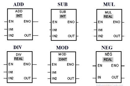
The tab shown below is visible in any language that you choose to write in this software. As seen in the below image, various categories of function blocks supported in this language are shown. Just click the function you require to use and that block will be placed in the sheet. It is pretty easy to use, instead of drag and drop. Once placed randomly by the software, you can then move the block to your required placement area.

function block elements in the functional block diagram

Now, refer to the below image. Once you have placed the function block, you can define what input and output tags to show in the sheet. When you place a function block and click the icon – view block properties placed in the top right corner of the block, you see the left-hand side image. Here, you can tick or untick the tags that need to be visible to the programmer for linking.

When you design an add-on defined function block, you see the right-hand side image. Here, there are two options – Req (required) And Vis (visible).In the required option, if ticked, you have to compulsorily link a tag to the pin, and it will be visible for sure. If not ticked, but the visible option is ticked, then you can just see the pin in your sheet. But, it will then not be compulsory to link a tag to the pin.

Tags in Functional Block Diagram in Studio 5000

How to manage tags in the functional block diagram of Studio 5000?

Similar to other languages in Studio 5000, when you place an undefined tag, you can create a new tag by right-clicking it and hitting the new option. Once a tag is placed, you can change it and assign a different one by double-clicking the tag and hitting the down arrow button as shown –

undefined tag in Studio 5000

Also, it is to be noted that you can assign both the tag or a constant in the reference element of the block diagram. These features are thus easy to use and makes the placement and managing of elements comfortable for a programmer.

In this way, we saw how to manage sheets, tags and elements in the functional block diagram. In the next and last post, we will see all the options of connecting blocks inside a sheet in the functional block diagram language of Studio 5000.

Read Next:

  • Car Wash Program Functional Block Diagram
  • Motor Starter Logic using Siemens Tia Portal
  • PLC to PLC Communication in Studio 5000
  • Seven Segment Display PLC Programming
  • PLC Example for Motor Interlocking Control
Don't Miss Our Updates
Be the first to get exclusive content straight to your email.
We promise not to spam you. You can unsubscribe at any time.
Invalid email address
You've successfully subscribed !

Continue Reading

#2 PLC Best Practices – Track Operating Modes
WHILE DO Statement in SCL Language
Types of Instructions in PLC Programming
Motor ON OFF Logic in PLC
How to Convert an Electrical Diagram into PLC Program?
How to Connect Mitsubishi FX3U PLC with Weinview MT6071iE HMI?
Share This Article
Facebook Whatsapp Whatsapp LinkedIn Copy Link
Share
Leave a Comment

Leave a Reply Cancel reply

Your email address will not be published. Required fields are marked *

Stay Connected

128.3kFollowersLike
69.1kFollowersFollow
210kSubscribersSubscribe
38kFollowersFollow

Categories

Explore More

Siemens Tia Portal PLC Training Course
Do’s and Don’ts in PLC
What Factors Affect the Choice of PLC Programming Software?
How to Interchange ON Delay Timer and OFF Delay Timer in a PLC
Comparison Instructions in PLC Programming
Site Commissioning Steps for PLC Programmers
PLC Motor Control Ladder Logic Programming
PLC Example on Switch Program with Timers

Keep Learning

Omron PLC painting program

Product Painting PLC Program using Omron CX-Programmer

Wonderware Recipe Manager Plus

What is Recipe Management in SCADA?

LES and GRT Blocks in PLC Programming

Allen Bradley Math Functions

Siemens Process Mode

Test and Process Modes in Siemens PLC

Control Speed of an Induction Motor using Analog Output of PLC

Control Speed of Induction Motor using Analog Output of PLC

Structured Text PLC Programming for Two-Tanks Level Control

Structured Text PLC Programming for Two-Tanks Level Application

PLC Memory Organization - Data Files and Program Files

PLC Memory Organization – Data Files and Program Files

Trolley and hoist PLC control

PLC Crane Movement Control with Limit Switches

Learn More

Examples of PLC Programming using Boolean Functions

Examples of PLC Programming using Boolean Functions

Solenoid-Valve-Working-Animation

Solenoid Valve Working Animation

Control Systems Interview Questions & Answers

Control Systems Interview Questions & Answers

Power Electronics Objective Questions

Thyristors Objective Questions and Answers

IS Loop Formula

Difference between Intrinsic Safe and Non-Intrinsic Safe Cables

Parallel Circuit

Parallel Circuit

Recurring Short Circuit Flash Overs Safety Hazards

Recurring Short Circuit Flash Overs Safety Hazards & Damages

Power System Protection and Relays Questions & Answers

Power System Protection and Relays Questions & Answers

Menu

  • About
  • Privacy Policy
  • Copyright

Quick Links

  • Learn PLC
  • Helping Hand
  • Part Time Job

YouTube Subscribe

Follow US
All rights reserved. Reproduction in whole or in part without written permission is prohibited.
Welcome Back!

Sign in to your account

Username or Email Address
Password

Lost your password?