Inst ToolsInst ToolsInst Tools
  • Courses
  • Automation
    • PLC
    • Control System
    • Safety System
    • Communication
    • Fire & Gas System
  • Instrumentation
    • Design
    • Pressure
    • Temperature
    • Flow
    • Level
    • Vibration
    • Analyzer
    • Control Valve
    • Switch
    • Calibration
    • Erection & Commissioning
  • Interview
    • Instrumentation
    • Electrical
    • Electronics
    • Practical
  • Q&A
    • Instrumentation
    • Control System
    • Electrical
    • Electronics
    • Analog Electronics
    • Digital Electronics
    • Power Electronics
    • Microprocessor
  • Request
Search
  • Books
  • Software
  • Projects
  • Process
  • Tools
  • Basics
  • Formula
  • Power Plant
  • Root Cause Analysis
  • Electrical Basics
  • Animation
  • Standards
  • 4-20 mA Course
  • Siemens PLC Course
Reading: Series Open Circuit Faults
Share
Font ResizerAa
Inst ToolsInst Tools
Font ResizerAa
  • Courses
  • Design
  • PLC
  • Interview
  • Control System
Search
  • Courses
  • Automation
    • PLC
    • Control System
    • Safety System
    • Communication
    • Fire & Gas System
  • Instrumentation
    • Design
    • Pressure
    • Temperature
    • Flow
    • Level
    • Vibration
    • Analyzer
    • Control Valve
    • Switch
    • Calibration
    • Erection & Commissioning
  • Interview
    • Instrumentation
    • Electrical
    • Electronics
    • Practical
  • Q&A
    • Instrumentation
    • Control System
    • Electrical
    • Electronics
    • Analog Electronics
    • Digital Electronics
    • Power Electronics
    • Microprocessor
  • Request
Follow US
All rights reserved. Reproduction in whole or in part without written permission is prohibited.
Inst Tools > Blog > Electrical Theory > Series Open Circuit Faults

Series Open Circuit Faults

Last updated: July 25, 2018 8:14 pm
Editorial Staff
Electrical Theory
No Comments
Share
1 Min Read
SHARE

Faults within a DC circuit will cause various effects, depending upon the nature of the fault. An understanding of the effects of these faults is necessary to fully understand DC circuit operation.

Series Open Circuit

A circuit must have a “complete” path for current flow, that is, from the negative side to the positive side of a power source. A series circuit has only one path for current to flow. If this path is broken, no current flows, and the circuit becomes an open circuit (Figure 53).

Electric Open Circuit

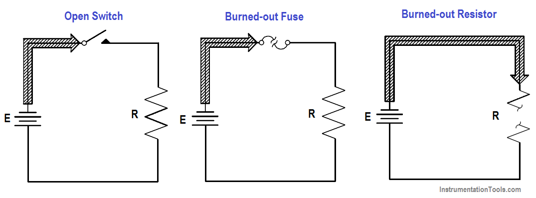
Figure 53 : Open Series Circuit

Circuits can be opened deliberately, such as by the use of a switch, or they may be opened by a defect, such as a broken wire or a burned-out resistor.

Since no current flows in an open series circuit, there are no voltage drops across the loads. No power is consumed by the loads, and total power consumed by the circuit is zero.

Don't Miss Our Updates
Be the first to get exclusive content straight to your email.
We promise not to spam you. You can unsubscribe at any time.
Invalid email address
You've successfully subscribed !

Continue Reading

Schematic Diagram
Series – Parallel Circuit Analysis
AC Generator Theory
DC Motor Speed
Starting of DC Motors
Three Phase AC Generators
Share This Article
Facebook Whatsapp Whatsapp LinkedIn Copy Link
Share
Leave a Comment

Leave a Reply Cancel reply

Your email address will not be published. Required fields are marked *

Stay Connected

128.3kFollowersLike
69.1kFollowersFollow
210kSubscribersSubscribe
38kFollowersFollow

Categories

Explore More

Magnetism
Power in Balanced 3 Phase Loads
Induction Motor Torque Versus Slip
Series-Wound DC Generators
Kirchhoff’s Laws
What is a circuit breaker ?
Impedance in RC Circuits
Parallel AC Generators

Keep Learning

Transformer Operation Under No-Load

Transformer Operation Under No-Load

Three Phase Wattmeter principle

Ampere Hour Meter

Three-Phase Wye Wiring System

4-Wire, Three-Phase Wye Wiring System

Ground Detector Lamp Method Principle

Ground Detector Principle

Shunt-Wound DC Generator Principle

Shunt-Wound DC Generators

Circuit Breaker Control Circuit Wiring

Circuit Breaker Control Circuit

Calculate Power in Parallel RL Circuit

Calculate Power in Parallel RL Circuit

Capacitive Time Constant for Charging Capacitor

Capacitive Time Constant

Learn More

Burner Control Loop Graphics

Burner Safety Logic for Initial Lighting

Sample Schematic Template for Systems Architecture Diagram

Design Document for Project Systems Architecture

Paddlewheel flowmeter principle

What is a Paddle Wheel Flow Meter?

Electrical Circuit Breaker Quiz

100 Electrical Circuit Breaker Quiz

Search tank in Intouch Scada

Tank Filling and Emptying using Intouch Scada Script

Instrument Numbering Philosophy

Instrument Numbering Philosophy

Comparison of Control Loops - Open, Closed, Cascade, Feedforward, Ratio

Comparison of Control Loops – Open, Closed, Cascade, Feedforward, Ratio

Bubbler Liquid Level Transmitter Calculation

Bubbler Liquid Level Transmitter Calculation

Menu

  • About
  • Privacy Policy
  • Copyright

Quick Links

  • Learn PLC
  • Helping Hand
  • Part Time Job

YouTube Subscribe

Follow US
All rights reserved. Reproduction in whole or in part without written permission is prohibited.
Welcome Back!

Sign in to your account

Username or Email Address
Password

Lost your password?