Inst ToolsInst ToolsInst Tools
  • Courses
  • Automation
    • PLC
    • Control System
    • Safety System
    • Communication
    • Fire & Gas System
  • Instrumentation
    • Design
    • Pressure
    • Temperature
    • Flow
    • Level
    • Vibration
    • Analyzer
    • Control Valve
    • Switch
    • Calibration
    • Erection & Commissioning
  • Interview
    • Instrumentation
    • Electrical
    • Electronics
    • Practical
  • Q&A
    • Instrumentation
    • Control System
    • Electrical
    • Electronics
    • Analog Electronics
    • Digital Electronics
    • Power Electronics
    • Microprocessor
  • Request
Search
  • Books
  • Software
  • Projects
  • Process
  • Tools
  • Basics
  • Formula
  • Power Plant
  • Root Cause Analysis
  • Electrical Basics
  • Animation
  • Standards
  • 4-20 mA Course
  • Siemens PLC Course
Reading: What is Sensor Trim and Output Trim in Smart Transmitter?
Share
Font ResizerAa
Inst ToolsInst Tools
Font ResizerAa
  • Courses
  • Design
  • PLC
  • Interview
  • Control System
Search
  • Courses
  • Automation
    • PLC
    • Control System
    • Safety System
    • Communication
    • Fire & Gas System
  • Instrumentation
    • Design
    • Pressure
    • Temperature
    • Flow
    • Level
    • Vibration
    • Analyzer
    • Control Valve
    • Switch
    • Calibration
    • Erection & Commissioning
  • Interview
    • Instrumentation
    • Electrical
    • Electronics
    • Practical
  • Q&A
    • Instrumentation
    • Control System
    • Electrical
    • Electronics
    • Analog Electronics
    • Digital Electronics
    • Power Electronics
    • Microprocessor
  • Request
Follow US
All rights reserved. Reproduction in whole or in part without written permission is prohibited.
Inst Tools > Blog > Calibration > What is Sensor Trim and Output Trim in Smart Transmitter?

What is Sensor Trim and Output Trim in Smart Transmitter?

Last updated: March 12, 2020 11:13 am
Editorial Staff
Calibration Pressure Measurement
1 Comment
Share
3 Min Read
SHARE

Analog electronic process transmitters typically have only two calibration adjustments: one for zero and another for span. Occasionally you may find an analog electronic transmitter with a third adjustment: one for linearity.

Contents
Smart TransmitterSensor Trim and Output Trim

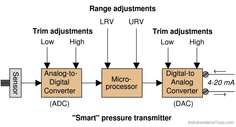
Modern “smart” process transmitters have more components in need of adjustment. A block diagram of a typical smart pressure transmitter shows this very clearly:

Smart Transmitter

Sensor Trim and Output Trim in Smart Transmitter

The purpose of the analog-to-digital converter (ADC) is to translate the pressure sensor’s electrical output signal into a digital number the microprocessor can understand.

Likewise, the purpose of the digital-to-analog converter (DAC) is to translate the digital output of the microprocessor into a 4 to 20 mA DC current signal representing measured pressure. The procedure of calibrating the ADC is called a sensor trim, while the process of calibrating the DAC is called an output trim.

Explain the importance of performing both a sensor trim and an output trim whenever calibrating a “smart” transmitter. In other words, explain why it is not enough to simply program LRV and URV values into the microprocessor (e.g. LRV = 0 PSI ; URV = 30 PSI) and declare the job finished.

Furthermore, explain what external calibration equipment must be connected to the transmitter to complete a sensor trim procedure, and also what external calibration equipment must be connected in order to complete an output trim procedure.

Sensor Trim and Output Trim

Simply setting the LRV and URV values is not actually calibrating the transmitter to accurately correspond to reality.

If this concept is hard to grasp, imagine a transmitter whose LRV and URV values are set perfectly, and whose DAC is calibrated just right, but whose ADC suffers from a zero shift. The microprocessor will “think” the pressure is something different from what it really is, and it will output an incorrect (zero-shifted) milliamp signal as a result.

In order to perform a sensor trim, you must connect a known pressure source (a standard) to the transmitter’s input port and correlate that standard pressure to the pressure value registered by the microprocessor.

When trimming the output, you must connect a precise milli-ammeter in series with the transmitter’s output current to correlate the intended current signal of the microprocessor to the actual current.

Credits: Tony R. Kuphaldt

Read Next:

  • HART Communicator Analysis
  • Square-Root in Flow Transmitter
  • What are Instrument Errors?
  • DP Level Transmitter Corrections
  • Linear to Square-root conversion
Don't Miss Our Updates
Be the first to get exclusive content straight to your email.
We promise not to spam you. You can unsubscribe at any time.
Invalid email address
You've successfully subscribed !

Continue Reading

Pressure Gauge Calibration Procedure
Gage and Absolute Pressure Transmitters Principle
Closed tank DP Level Transmitter with wet leg Zero elevation Calibration
How to do calibration checks of vibration Probe, extension cable and vibration monitor
DP type Flow Transmitter Preventive Maintenance and Calibration
What is calibration?
Share This Article
Facebook Whatsapp Whatsapp LinkedIn Copy Link
Share
1 Comment
  • MohdKusno says:
    September 9, 2020 at 4:09 am

    Learn instrument

    Reply

Leave a Reply Cancel reply

Your email address will not be published. Required fields are marked *

Stay Connected

128.3kFollowersLike
69.1kFollowersFollow
210kSubscribersSubscribe
38kFollowersFollow

Categories

Explore More

Closed Tank Remote Seal Capillary type DP Transmitter
Diaphragm Seal Material Selection
Differential Pressure Switch Principle
Transmitter Calibration Procedure
Components of Bourdon Tube – Questions and Answers
Basics of Differential Pressure Transmitters
Portable Gas Detectors Calibration Procedure
Pressure Transmitters Purged impulse lines

Keep Learning

Smart Transmitter Calibration Tutorial Part 2

Smart Transmitter Calibration Tutorial Part 2

Calibrating Transmitter System One Seal with suppressed Zero

Calibrating Level Transmitter with Remote Seals

Effects of Capillary Tubing on Pressure Measurement

Capillary Tubing Pressure Sensor Temperature & Elevation Problems

Types of Pressure

Types of Pressure – Instrument Questions and Answers

pressure transmitter calibration setup

Questions on Pressure Transmitter Calibration Setup

Uncertainty Calculations of Pressure Calibration

Uncertainty Calculations of Pressure Calibration

As-found and As-left Calibration

As-found and As-left Documentation during Calibration

Types of Calibration

Types of Calibration

Learn More

Semiconductor Fuse

What is a Semiconductor Fuse?

Dall Tube Flow Meter Working Principle

Dall Tube Flow Meter – Principle, Advantages, Disadvantages

Loop Diagram

15 Loop Diagram Questions

Intrinsic Safe Calculation

Intrinsic Safe Calculation

DeadWeight Tester

DeadWeight Tester Questions

NAMUR NE 43

What is NAMUR NE 43?

Alternative Optical Proximity Sensor

Proximity Sensor

Basics of Electricity Rates

Basics of Electricity Rates

Menu

  • About
  • Privacy Policy
  • Copyright

Quick Links

  • Learn PLC
  • Helping Hand
  • Part Time Job

YouTube Subscribe

Follow US
All rights reserved. Reproduction in whole or in part without written permission is prohibited.
Welcome Back!

Sign in to your account

Username or Email Address
Password

Lost your password?