Inst ToolsInst ToolsInst Tools
  • Courses
  • Automation
    • PLC
    • Control System
    • Safety System
    • Communication
    • Fire & Gas System
  • Instrumentation
    • Design
    • Pressure
    • Temperature
    • Flow
    • Level
    • Vibration
    • Analyzer
    • Control Valve
    • Switch
    • Calibration
    • Erection & Commissioning
  • Interview
    • Instrumentation
    • Electrical
    • Electronics
    • Practical
  • Q&A
    • Instrumentation
    • Control System
    • Electrical
    • Electronics
    • Analog Electronics
    • Digital Electronics
    • Power Electronics
    • Microprocessor
  • Request
Search
  • Books
  • Software
  • Projects
  • Process
  • Tools
  • Basics
  • Formula
  • Power Plant
  • Root Cause Analysis
  • Electrical Basics
  • Animation
  • Standards
  • 4-20 mA Course
  • Siemens PLC Course
Reading: Instrument Protection Methods: Seals
Share
Font ResizerAa
Inst ToolsInst Tools
Font ResizerAa
  • Courses
  • Design
  • PLC
  • Interview
  • Control System
Search
  • Courses
  • Automation
    • PLC
    • Control System
    • Safety System
    • Communication
    • Fire & Gas System
  • Instrumentation
    • Design
    • Pressure
    • Temperature
    • Flow
    • Level
    • Vibration
    • Analyzer
    • Control Valve
    • Switch
    • Calibration
    • Erection & Commissioning
  • Interview
    • Instrumentation
    • Electrical
    • Electronics
    • Practical
  • Q&A
    • Instrumentation
    • Control System
    • Electrical
    • Electronics
    • Analog Electronics
    • Digital Electronics
    • Power Electronics
    • Microprocessor
  • Request
Follow US
All rights reserved. Reproduction in whole or in part without written permission is prohibited.
Inst Tools > Blog > Instrumentation Design > Instrument Protection Methods: Seals

Instrument Protection Methods: Seals

Last updated: October 20, 2020 5:13 pm
Editorial Staff
Instrumentation Design Pressure Measurement
No Comments
Share
6 Min Read
SHARE

Here we shall see recommended practices for the protection of the instrument from harsh process conditions. In this article, we shall learn about Diaphragm seal and liquid seal methods to protect the instrument.

Contents
Diaphragm SealSealsLiquid Seals

A seal can be a mechanical isolator between process and instrument or it can be part of piping filled with fluid.

These protection methods are generally used with pressure transmitters, DP transmitters, pressure gauges, and piping that connects these instruments to the process.

Diaphragm Seal

Diaphragm seals are used in the following cases.

  • When process fluid must be isolated
  • Slurry services
  • Toxic/corrosive services
  • High-temperature fluid.
  • When fluid has the tendency to clog or freeze in ambient temperatures.

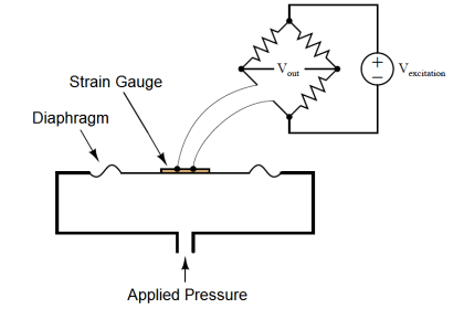
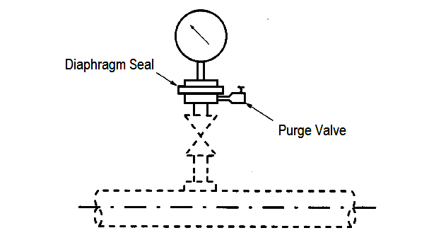
Pressure-gauge and pressure-switch seals (see Figure below) usually consist of a diaphragm and a diaphragm holder into which the instrument is connected, a seal fluid is enclosed in the chamber between the diaphragm and the gauge. The holder, diaphragm, and gasket materials are selected to be compatible with the process fluid (silicon oil mostly).

The diaphragm is generally welded into the holder, but it may also be clamped and gasketed. The seal fluid should be non-flammable, have low vapor pressure and thermal expansion, and in the case of a diaphragm rupture, be compatible with and non-contaminating to the process.

Diaphragm Seal

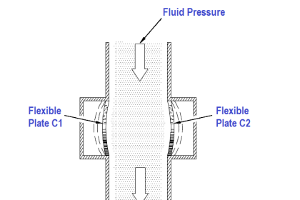
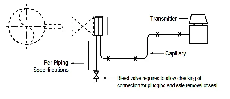
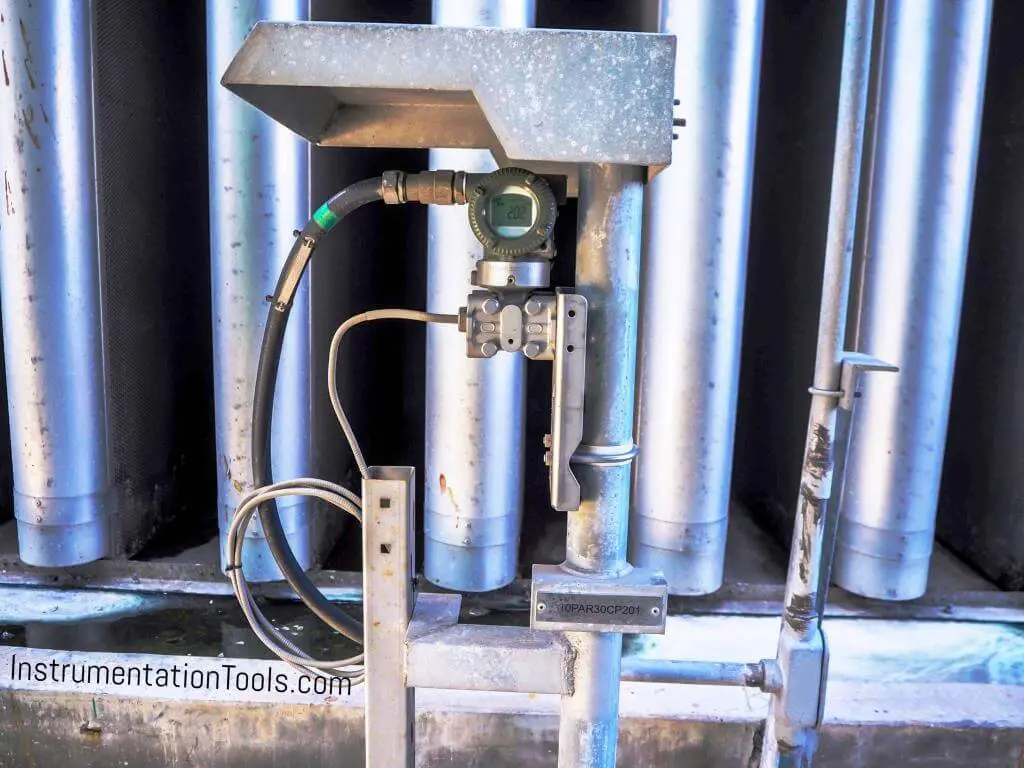
Seals for pressure and differential-pressure transmitters are available in a variety of configurations. A common style is a diaphragm mounted in a wafer, clamped between piping flanges, and connected to the transmitter with an armoured capillary (see Figure below). This style, which uses two seals, is used for flow metering and level measurement in vessels under pressure or vacuum.

In some applications, capillaries can be as long as 35 feet (10 meters). To avoid measurement errors, it is necessary to select capillaries of equal length and maintain them at the same temperature. To maintain a good response and minimize temperature gradients on the capillaries, the capillary length should be as short as possible.

Pressure Transmitter Seal

A similar style, which uses one seal, is used to measure pressure or the differential pressure between two streams when only one stream requires a seal. Measurement of differential pressure between combustion fuel oil and atomizing steam is an example of this application.

The level in atmospheric tanks can be measured with a seal assembly attached directly to the transmitter body. When no condensable materials are contained in the vapor space above the liquid, it is possible to connect a reference line to the low-pressure side of the transmitter and use it for measurement in a vessel under pressure.

Whenever it has been determined that a diaphragm seal is required, the user should work closely with the supplier to ensure that the instrument configuration is appropriate for the application. Care should be taken to ensure that the seal fluid will operate over the required temperature range and be compatible with the process.

Seals

Pressure Transmitter Seal

Liquid Seals

In many standard transmitter installations, the seal is the process fluid. Most liquid flowmeters, steam meters, and condensable-vapor meters are sealed in this manner. The liquid cools, and the transmitter is not subjected to the process temperature.

In many locations where steam is used, the condensed water must be protected from freezing. Whenever possible, the process fluid is the most desirable seal liquid, since fresh supply is readily available if the seal is lost through leakage or dis-operation.

If a process stream contains hydrocarbons and water, it is likely that the fluid in the impulse lines will separate into two phases. If the transmitter is a flowmeter, different amounts of water could accumulate in the two sections of the piping, which could result in measurement errors. To prevent this, the piping should be filled with water or an ethylene-glycol- water mix, or else water-dropout pots should be used. In many locations, the use of glycol-water can eliminate the need for heating.

The seal fluid must be compatible with the process stream. The selected fluid must have a density higher than that of the process stream. It should be non-corrosive and have a low vapor pressure at the process temperature. Whenever non- process seal fluids are used, permanent warning tags or a special paint color should be used to indicate that a special seal fluid is enclosed.

Interest to add any further points? Share with us through below comments section.

Author: Kalpit Patel

Read Next:

  • Chemical Seal Pressure Transmitter
  • Diaphragm Seal Material
  • Remote Diaphragm Seal Transmitter
  • Orifice Plate Flow Requirement
  • Pressure Control Loop Problems
Don't Miss Our Updates
Be the first to get exclusive content straight to your email.
We promise not to spam you. You can unsubscribe at any time.
Invalid email address
You've successfully subscribed !

Continue Reading

How to Select an Actuator for Valve
Compliance Table Application (for Procurement Service Cycle)
DP Transmitter Block and Bleed Valves
What is Sensor Trim and Output Trim in Smart Transmitter?
Determine the Status of Lamps and Relays in the Circuit ?
Vendor View of Supplying Industrial Process Control & Safety Systems
Share This Article
Facebook Whatsapp Whatsapp LinkedIn Copy Link
Share
Leave a Comment

Leave a Reply Cancel reply

Your email address will not be published. Required fields are marked *

Stay Connected

128.3kFollowersLike
69.1kFollowersFollow
210kSubscribersSubscribe
38kFollowersFollow

Categories

Explore More

Thermowell Insertion and Immersion Length
Role of an Instrumentation Design Engineer for Beginners
Foundation Fieldbus Pressure Transmitter Configuration
Instrumentation and Process Teams Interactions in Design Engineering Companies
Information on the Pressure Gauge Dial
DeadWeight Tester Questions
System Architecture and Process Control Systems Philosophy
Differences between No-load Supply Current and Load Current

Keep Learning

differential-pressure-transmitter-calibration-procedure

Differential Pressure Transmitter Calibration Procedure

Multiple Thermowell Installations Problems

Multiple Thermowell Installations Problems

How to Calculate Heat Load In Electrical Panel

How to Calculate Heat Load in Electrical/Electronic Panel Enclosure

Readings Mismatch between Field & Control Room

Readings Mismatch between Field & Control Room ? Why

Avoid Process Downtime With Five Device Protection Considerations

How to Avoid Process Downtime ?

Inclined-limb Manometer Formula - 2

Inclined-limb Manometer Principle

Scaling Sensor Output to Engineering Units

Scaling Sensor Output to Engineering Units

Instrument Air Calculations

Basic Calculations of Instrument Air

Learn More

Start Stop of one Motor from same Push button PLC program

Start Stop of one Motor from the same Push button PLC program

pressure-gauge-animation

Bourdon Tube Pressure Gauge Working Principle Animation

how-a-4-20ma-transmitter-works

How a 4-20mA Transmitter Works?

User Defined Function Blocks in PLC

What are User Defined Function Blocks in PLC?

Heat Exchanger Root Cause Analysis

Heat Exchanger Root Cause Analysis (RCA)

Electrical Machines Questions and Answers

Synchronous Machines Efficiency Questions

PID Controller Gains Effect on Setpoint

PID Controller Gains Effect on Manipulated Variable

Purpose of Flow Ratio Controller

Identify the Purpose of Flow Ratio Controller

Menu

  • About
  • Privacy Policy
  • Copyright

Quick Links

  • Learn PLC
  • Helping Hand
  • Part Time Job

YouTube Subscribe

Follow US
All rights reserved. Reproduction in whole or in part without written permission is prohibited.
Welcome Back!

Sign in to your account

Username or Email Address
Password

Lost your password?