In the posts on inductance and capacitance, we have learned that both conditions are reactive and can provide opposition to current flow, but for opposite reasons. Therefore, it is important to find the point where inductance and capacitance cancel one another to achieve efficient operation of AC circuits.
Resonance occurs in an AC circuit when inductive reactance and capacitive reactance are equal to one another: XL = XC. When this occurs, the total reactance, X = XL – XC becomes zero and the impendence is totally resistive. Because inductive reactance and capacitive reactance are both dependent on frequency, it is possible to bring a circuit to resonance by adjusting the frequency of the applied voltage. Resonant frequency (fRes) is the frequency at which resonance occurs, or where XL = XC .
The below Equation is the mathematical representation for resonant frequency.
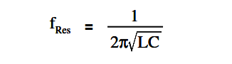
where
fRes = resonant frequency (Hz)
L = inductance (H)
C = capacitance (f)
Figure 9 : Simple R-C-L Circuit
In a series R-C-L circuit, as in Figure 9, at resonance the net reactance of the circuit is zero, and the impedance is equal to the circuit resistance; therefore, the current output of a series resonant circuit is at a maximum value for that circuit and is determined by the value of the resistance. (Z=R)
Resonance in a parallel R-C-L circuit will occur when the reactive current in the inductive branches is equal to the reactive current in the capacitive branches (or when XL = XC ). Because inductive and capacitive reactance currents are equal and opposite in phase, they cancel one another at parallel resonance.
Figure 10 : Simple Parallel R-C-L Circuit
If a capacitor and an inductor, each with negligible resistance, are connected in parallel and the frequency is adjusted such that reactances are exactly equal, current will flow in the inductor and the capacitor, but the total current will be negligible.
The parallel C-L circuit will present an almost infinite impedance. The capacitor will alternately charge and discharge through the inductor. Thus, in a parallel R-C-L, as in Figure 10, the net current flow through the circuit is at minimum because of the high impendence presented by XL and XC in parallel.
The conveyor sorting machine is widely used in the packing industries using the PLC program…
Learn the example of flip-flop PLC program for lamps application using the ladder logic to…
In this article, you will learn the STAR DELTA programming using PLC controller to start…
Lube oil consoles of rotary equipment packages in industrial process plants are usually equipped with…
Rotating equipment packages such as pumps, compressors, turbines need the lube oil consoles for their…
This article explains how to blink lights in ladder logic with a detailed explanation video…


