Inst ToolsInst ToolsInst Tools
  • Courses
  • Videos
  • Q & A
    • Interview
      • Instrumentation
      • Electronics
      • Electrical
      • Practical Questions
    • MCQ
      • Instrumentation MCQ
      • Electrical MCQ
      • Electronics MCQ
      • Control Systems MCQ
      • Analog Electronics MCQ
      • Digital Electronics MCQ
      • Power Electronics MCQ
      • Microprocessor MCQ
      • Multiple Choice Questions
  • EE
    • Electronics
      • Electronics Q & A
      • Electronic Basics
      • Electronic Devices & Circuits
      • Electronics Animation
      • Digital Electronics
    • Electrical
      • Electrical Basics
      • Electrical Q & A
      • Power Electronics
      • Electrical Machines
      • Electrical Animation
      • Power Systems
      • Switchgear & Protection
      • Transmission & Distribution
  • Measure
    • Control Valves
    • Calibration
    • Temperature
    • Pressure
    • Flow
    • Level
    • Analyzers
    • Switches
    • Vibration
    • Solenoid Valve
  • Control
    • PLC Tutorials
    • Control Systems
    • Safety Instrumented System (SIS)
    • Communication
    • Fire & Gas System
  • More
    • Design
    • Tools
    • Animation
    • Basics
    • Formulas
    • Standards
    • TextBooks
    • Common
    • Software
    • Excel Tools
    • Erection & Commissioning
    • Process Fundamentals
    • Videos
    • Books
Search
All rights reserved. Reproduction in whole or in part without written permission is prohibited.
Reading: How Does Redundant Power Supply Work?
Share
Notification Show More
Font ResizerAa
Inst ToolsInst Tools
Font ResizerAa
  • Courses
  • PLC Tutorials
  • Control Systems
Search
  • Courses
  • Videos
  • Q & A
    • Interview
    • MCQ
  • EE
    • Electronics
    • Electrical
  • Measure
    • Control Valves
    • Calibration
    • Temperature
    • Pressure
    • Flow
    • Level
    • Analyzers
    • Switches
    • Vibration
    • Solenoid Valve
  • Control
    • PLC Tutorials
    • Control Systems
    • Safety Instrumented System (SIS)
    • Communication
    • Fire & Gas System
  • More
    • Design
    • Tools
    • Animation
    • Basics
    • Formulas
    • Standards
    • TextBooks
    • Common
    • Software
    • Excel Tools
    • Erection & Commissioning
    • Process Fundamentals
    • Videos
    • Books
Follow US
All rights reserved. Reproduction in whole or in part without written permission is prohibited.
Inst Tools > Blog > PLC Tutorials > How Does Redundant Power Supply Work?

How Does Redundant Power Supply Work?

Understand the importance of a Redundant Power Supply in industrial PLC automation for uninterrupted operations and critical applications.

Last updated: March 16, 2025 8:29 am
Viral Nagda
PLC Tutorials
No Comments
Share
6 Min Read
SHARE

In industrial PLC automation, there are many applications that are critical in nature and require a non-stop power supply for operation. Even a few minutes of lag in supply can disrupt the whole plant operation. Now, when we talk of backup power supplies, we always remember UPS first. But, there are other options apart from a normal inverter too. As PLC and instrumentation normally use a 24V DC supply for operation, redundant power supplies or SMPS are also available for providing a power backup operation. In this post, we will see how a redundant power supply works.

Contents
Why is SMPS used in the control panel?How does redundant SMPS work?

Why is SMPS used in the control panel?

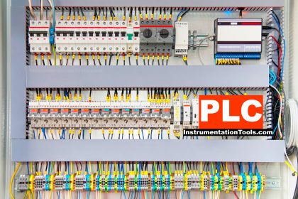
First of all, let us understand why SMPS is used in a control panel. Most of the components inside a PLC panel or instrumentation panel are small-rating devices like PLC, HMI, relays, instrument power supply, isolators, barriers, etc. They mostly require a 24V DC supply for their operation. To fulfill this purpose, a device called SMPS is used in the control panel. SMPS stands for switched mode power supply. It is a rectifier that converts the 110-230V AC supply into a 5-24V DC supply. 5V is rarely used (only for very small current rating devices); so the most general output is 24V.

An SMPS takes an AC supply as input, and in return gives you a 24V DC output. It has an adjustable screw knob, where you can adjust the output DC voltage within a tolerable range (mostly between 21-27V DC). Also, this adjustment is fine; so you can even set the output voltage to 23.5 V. Due to this, you get more flexibility in controlling the final DC voltage according to your requirements. Just consider the full load current ratings that all your DC instruments will consume (can vary from 5A to even 30A). Accordingly, choose SMPS for your control panel. Advanced SMPS also has a relay contact, which is normally open when the SMPS is giving the desired output. But if the output goes out of range, then this contact closes, which can then be used by the PLC as a digital input for further control.

How does redundant SMPS work?

Redundant Power Supply

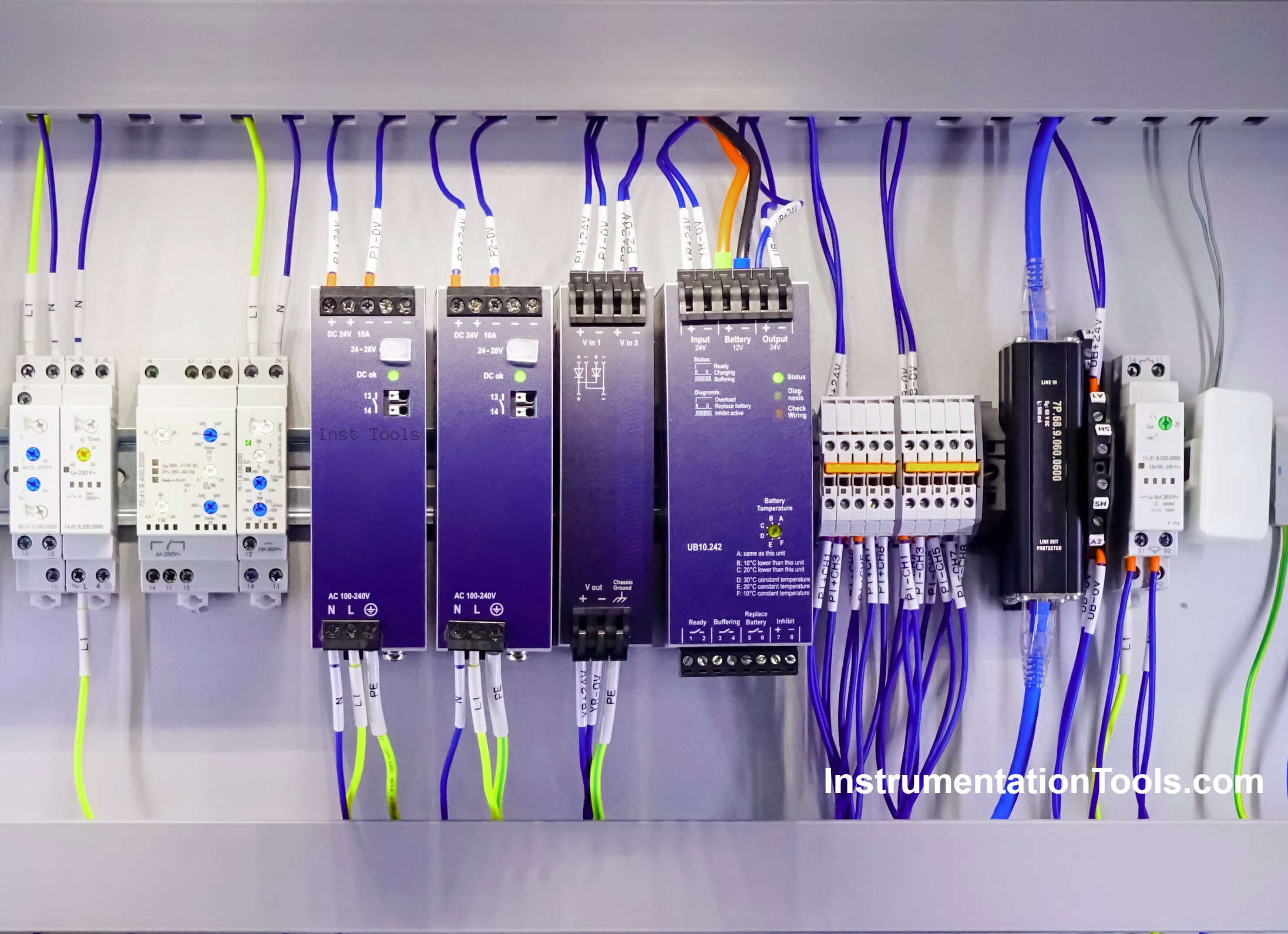
As the name suggests, a redundant SMPS means that there are two sets of power supplies, one acting as primary and the other acting as standby. The primary power supply will give power to the whole panel requirement. The standby power supply will come into the picture when the primary one fails immediately. This is possible through the use of diodes. The incoming AC supply is distributed to both the power supplies. At the output of each supply, a diode is placed. The voltage of the primary power supply (24V for example) is kept a little bit higher than the standby power supply (23.5V for example). The diodes work in synchronization with each other and compare the voltage present across them. One with the higher voltage will pass the voltage, and the other one will block the voltage.

In this case, the primary SMPS diode will pass the voltage in normal conditions. If it fails due to any reason and is not able to generate enough voltage now, then the standby SMPS diode will take over and pass the voltage. Now, if the primary SMPS again becomes healthy, then as its voltage was set higher, it’s diode will again take over and pass the voltage to the load. So, in this way, both the diodes work in tandem and pass the voltage to the load respectively.

Now, this structure comes in two types – in the first one, both the SMPS come in a single package where they are designed accordingly to work in redundancy (including diodes and all); and in the second one, you can use two normal SMPS’s individually too. But then, you will have to connect a diode module at both the outputs, designed in such a way that they work in redundancy (it is available readymade in the market). So, while shifting from primary to standby or vice-versa, there is no blockage of the load power supply, and goes uninterrupted.

In this way, we saw how a redundant power supply works.

Read Next:

  • Why does SMPS Need isolation?
  • Select the Encoder for Your Machine
  • PLC Logic for Control Spray Nozzle and Fans
  • Automation Solutions for Stairway Lighting
  • PLC Water Pumping and Chemical Solution
Don't Miss Our Updates
Be the first to get exclusive content straight to your email.
We promise not to spam you. You can unsubscribe at any time.
Invalid email address
You've successfully subscribed !

Recommended Articles

Positive and Negative Edges using Statement List Language
Procedure for Connecting Allen Bradley PLC and PC – RS Logix 500
How to Create Templates in FactoryTalk View Studio?
Conveyor Sorting Machine PLC Program with Calculation Function
Why is 24 Volts Commonly used in PLC Systems?
SCADA Hardware and Software
Share This Article
Facebook Whatsapp Whatsapp LinkedIn Copy Link
Share
Leave a Comment

Leave a Reply Cancel reply

Your email address will not be published. Required fields are marked *

Stay Connected

128.3kFollowersLike
69.1kFollowersFollow
208kSubscribersSubscribe
38kFollowersFollow

Categories

Recent Comments

  • William Snyder on Top Non-PLC Certification Courses for Automation Professionals
  • Kamli on Top Free PLC Software
  • Guifty Shimica on Top Non-PLC Certification Courses for Automation Professionals
  • Guifty Shimica on Top Non-PLC Certification Courses for Automation Professionals

Related Articles

Introduction to SCL Programming in Siemens PLC

Types of Expressions in the SCL Language of the Tia Portal

VFD Interview Questions and Answers

VFD Interview Questions and Answers – Electrical Drives

SCADA Software and their Comparison

SCADA Software and their Comparison

PLC Tag Naming Conventions

PLC Tag Naming Conventions

PID Simulator

PID Simulator Download

Create Ladder Diagram from Boolean Logic

Create Ladder Diagram from Boolean Logic

AENT Module in Rockwell PLC

AENT Module in Rockwell PLC – Remote IO Adapter

PLC Control Panel

Inside the PLC Control Panel: How Much Do You Know?

More Articles

toroidal conductivity probe principle

Conductivity Analyzer Common Problems and Troubleshooting Tips

NEMA to IP Ratings

NEMA Enclosure Types Standards

Free Schneider PLC Training - Automation Course

Free Schneider PLC Training – Automation Course

Negative Readings in Gas Detectors

Why Negative Readings in Gas Detectors ?

Smart Drip Irrigation System Using PLC

Scheduled Daily Plant Watering PLC Program

ISO 5167 Orifice Plate Types

Readers Questions on Flow Transmitter

Insulation Resistance Test

What is an Insulation Resistance Test? – Types, Applications

5 Valve manifold

5 Valve Manifold Operation

Follow US
All rights reserved. Reproduction in whole or in part without written permission is prohibited.
Welcome Back!

Sign in to your account

Username or Email Address
Password

Lost your password?