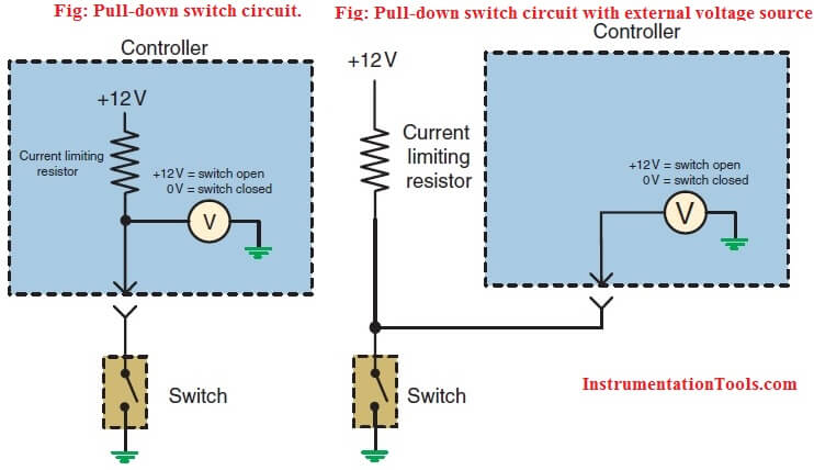
Switches are simplest of all input devices. The Digital Input Card monitors the two states of the switch by measuring the voltage on the sense circuit.
There are two types of voltage sensing circuits used with switches;
Basically, the pull-down circuit will close the switch to ground and the pull-up circuit will close the switch to voltage.

A pull-down voltage sense circuit usually uses an internal voltage source within the processor card. It is also possible to use an external voltage source. The current limiting resistor is used to protect the processor card and the circuit. It also prevents input values from floating. Floating occurs when the switch is open resulting in the input to the voltage sense circuit of the control module being susceptible to electrical noise that may cause the control module to misread the switch state. The current limiting resistor used in the circuit is referred to as a pull-up resistor since it assures the proper high voltage reading by connecting the voltage sense circuit to an electrical potential that can be removed when the switch is closed.
The pull-up resistor is usually of a very high ohms value to keep amperage to a minimum.
This resistor can have a value of 10K to 10M ohms. When the switch is open, there is no current flow through the resistor and no voltage drop over it. This results in the voltage sense circuit recording a value equal to the reference voltage. When the switch is closed, current flows through the resistor and results in a voltage drop. Since the switch should provide a clean contact to ground, the voltage sense circuit should read a value close to 0 volts.
The pull-up circuit will have a reference voltage through the switch. Usually the reference voltage will be provided directly from the battery or by the ignition switch. The current limiting resistor performs the same function in this circuit as it does in the pull-down circuit. This resistor is referred to as a pull-down resistor since it assures a proper low voltage reading by preventing float when the switch is open. With the switch in the open position the voltage sense circuit will read 0 volts. With the switch closed, the sense circuit should read close to reference voltage.
Both of these circuits are limited concerning the ability to determine circuit faults. Since there are only two states for the switch, there are two voltage values that the processor card expects to see. An open or short to ground will not produce an unexpected voltage value, but will result in improper system operation. However, the processor card may be capable of determining an functionality problem with the input circuit if the seen voltage is implausible for the conditions. For example, if the switch is an operator activated switch that requests A/C operation and the voltage indicates that the switch may be stuck the processor card can set a stuck switch DTC and ignore the input.
To provide continuity diagnostics, the circuit may have a diagnostic resistor wired parallel to the switch. The processor card will be able to recognize three different voltage values. In the example, the current limiting resistor has a value of 10K ohms while the diagnostic resistor has a value of 2K ohms. With the switch in the open state, the voltage sense circuit would read 10 volts. With the switch closed the voltage read will be close to 0 volts. A reading of 12 volts would indicate an open in the circuit.
Another typical type of switch that is used is the resistive multiplex switch. This switch is used to provide multiple inputs from a single switch using one circuit. The control module sends a signal voltage to the switch through a fixed resistor. Each switch position has an unique resistance value that will be placed in series with the resistor in the control module. As different switch positions are selected, a different amount of voltage is dropped over the fix resistor in the control module and the sensed voltage level changes. Based on the sensed voltage value, the control module interprets what operation the driver is requesting.
Also Read: Basics of Switches
The conveyor sorting machine is widely used in the packing industries using the PLC program…
Learn the example of flip-flop PLC program for lamps application using the ladder logic to…
In this article, you will learn the STAR DELTA programming using PLC controller to start…
Lube oil consoles of rotary equipment packages in industrial process plants are usually equipped with…
Rotating equipment packages such as pumps, compressors, turbines need the lube oil consoles for their…
This article explains how to blink lights in ladder logic with a detailed explanation video…