This article discusses product painting machines using Counter and Timer Instructions in CX-Programmer.
Product Painting PLC Program
This program has 5 buttons and 3 sensors, START_SYSTEM (0.00) button is used to Turn On the system, STOP_SYSTEM (0.01) button is used to Turn Off the system, RESET_RED_COUNTER (0.05) button is used to reset data in the memory word RED_COUNTER (D0), RESET_BLUE_COUNTER (0.06) is used to reset data in the memory word BLUE_COUNTER (D1), and RESET_GREEN_COUNTER (0.07) button is used to reset data in the memory word GREEN_COUNTER (D2).
The SENS_RED (0.02) sensor is used to Turn On the Red sprayer, the SENS_BLUE (0.03) sensor is used to Turn On the Blue sprayer, and the SENS_GREEN (0.04) sensor is used to Turn On the Green sprayer.
Each product carried by the conveyor will be painted in the order of Red, Blue, and Green.
In this program, when the START_SYSTEM (0.00) button is pressed, the system will Run and the Output CONVEYOR (100.00) will be ON.
When the SENS_RED (0.02) Sensor detects the product, the RED_SPRAYER (100.01) Output will be ON for 3 Seconds and will be recorded in the memory word RED_COUNTER (D0).
When the SENS_BLUE (0.03) Sensor detects the product, the BLUE_SPRAYER (100.02) Output will be ON for 4 Seconds and will be recorded in the memory word BLUE_COUNTER (D1).
When the SENS_GREEN (0.04) Sensor detects the product, the GREEN_SPRAYER (100.03) Output will be ON for 5 Seconds and will be recorded in the memory word GREEN_COUNTER (D2).
Inputs and Outputs
| Comment | Input (I) | Output(Q) | Memory Bits | Memory Words | Timers |
| START_SYSTEM | 0.00 | ||||
| STOP_SYSTEM | 0.01 | ||||
| SENS_RED | 0.02 | ||||
| SENS_BLUE | 0.03 | ||||
| SENS_GREEN | 0.04 | ||||
| RESET_RED_COUNTER | 0.05 | ||||
| RESET_BLUE_COUNTER | 0.06 | ||||
| RESET_GREEN_COUNTER | 0.07 | ||||
| CONVEYOR | 100.00 | ||||
| RED_SPRAYER | 100.01 | ||||
| BLUE_SPRAYER | 100.02 | ||||
| GREEN_SPRAYER | 100.03 | ||||
| TIMER_RED | T0000 | ||||
| TIMER_BLUE | T0001 | ||||
| TIMER_GREEN | T0002 | ||||
| SYSTEM_ON | W0.00 | ||||
| RED_COUNTER | D0 | ||||
| BLUE_COUNTER | D1 | ||||
| GREEN_COUNTER | D2 |
PLC Program using Omron CX-Programmer
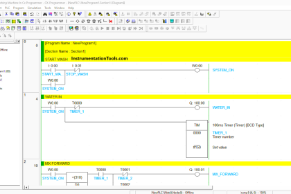
RUNG 0 (SYSTEM_ON)
In this Rung, when START_SYSTEM (0.00) button is pressed, the memory bit SYSTEM_ON (W0.00) will become a HIGH state. Because it uses latching, the memory bit SYSTEM_ON (W0.00) remains in the HIGH state even though the START_SYSTEM (0.00) button has been Released.
The memory bit SYSTEM_ON (W0.00) will change to a LOW state if the STOP_SYSTEM (0.01) button is Pressed.
RUNG 1 (CONVEYOR ON)
When the NO contact of memory bit SYSTEM_ON (W0.00) is in the HIGH state, the CONVEYOR (100.00) Output becomes ON.
RUNG 2 (RED SPRAY)
In this Rung, when the NO contact of memory bit SYSTEM_ON (W0.00) and SENS_RED (0.02) sensor in the HIGH state, the RED_SPRAYER (100.01) Output will be ON and the timer TIMER_RED (T0000) will start counting up to 3 seconds.
The RED_SPRAYER (100.01) Output will remain ON even though the SENS_RED (0.02) sensor is in the LOW state because it uses Latching. The RED_SPRAYER (100.01) Output will be OFF when the timer TIMER_RED (T0000) has finished counting.
RUNG 3 (BLUE SPRAY)
In this Rung, when the NO contact of memory bit SYSTEM_ON (W0.00) and SENS_BLUE (0.03) sensor is in the HIGH state, the BLUE_SPRAYER (100.02) Output will be ON and the timer TIMER_BLUE (T0001) will start counting up to 4 seconds.
The BLUE_SPRAYER (100.02) Output will remain ON even though the SENS_BLUE (0.03) sensor is in the LOW state because it uses Latching. The BLUE_SPRAYER (100.02) Output will be OFF when the timer TIMER_BLUE (T0001) has finished counting.
RUNG 4 (GREEN SPRAY)
In this Rung, when the NO contact of memory bit SYSTEM_ON (W0.00) and SENS_GREEN (0.04) sensor in the HIGH state, the GREEN_SPRAYER (100.03) Output will be ON and the timer TIMER_GREEN (T0002) will start counting up to 5 seconds.
The GREEN_SPRAYER (100.03) Output will remain ON even though the SENS_GREEN (0.04) sensor is in the LOW state because it uses Latching. The GREEN_SPRAYER (100.03) Output will be OFF when the timer TIMER_GREEN (T0002) has finished counting.
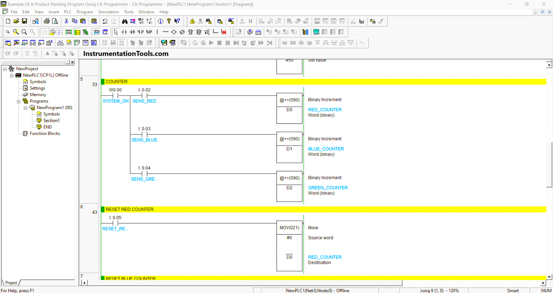
RUNG 5 (COUNTER)
When the NO contact of memory bit SYSTEM_ON (W0.00) and SENS_RED (0.02) sensor in HIGH state, the value in memory word RED_COUNTER (D0) will increase (+1).
When the SENS_BLUE (0.03) sensor is in a HIGH state, then the value in memory word BLUE_COUNTER (D1) will increase (+1).
When the SENS_GREEN (0.04) sensor is in a HIGH state, then the value in memory word GREEN_COUNTER (D2) will increase (+1).
RUNG 6 (RESET RED COUNTER)
In this rung, if the RESET_RED_COUNTER (0.05) button is pressed, the data in memory word RED_COUNTER (D0) will be reset to zero “0”.
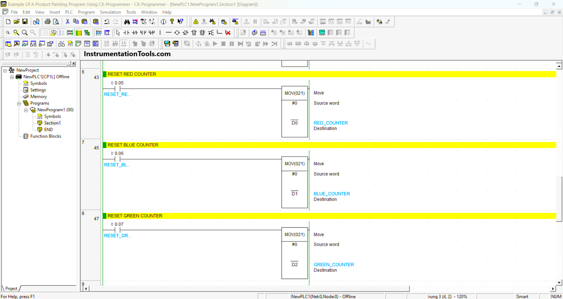
RUNG 7 (RESET BLUE COUNTER)
In this rung, if the RESET_BLUE_COUNTER (0.06) button is pressed, the data in memory word BLUE_COUNTER (D1) will be reset to zero “0”.
RUNG 8 (RESET GREEN COUNTER)
In this rung, if the RESET_GREEN_COUNTER (0.07) button is pressed, the data in memory word GREEN_COUNTER (D2) will be reset to zero “0”.
Read Next:
- Studio 5000 Motor Running Hours PLC Logic
- STAR-DELTA Auto And Manual PLC Program
- CX-Programmer Products Sorting & Counting
- PLC 1 Button To Activate 4 Different Machines
- Electric Motor Forward Reverse PLC Logic