Inst ToolsInst ToolsInst Tools
  • Courses
  • Videos
  • Q & A
    • Interview
      • Instrumentation
      • Electronics
      • Electrical
      • Practical Questions
    • MCQ
      • Instrumentation MCQ
      • Electrical MCQ
      • Electronics MCQ
      • Control Systems MCQ
      • Analog Electronics MCQ
      • Digital Electronics MCQ
      • Power Electronics MCQ
      • Microprocessor MCQ
      • Multiple Choice Questions
  • EE
    • Electronics
      • Electronics Q & A
      • Electronic Basics
      • Electronic Devices & Circuits
      • Electronics Animation
      • Digital Electronics
    • Electrical
      • Electrical Basics
      • Electrical Q & A
      • Power Electronics
      • Electrical Machines
      • Electrical Animation
      • Power Systems
      • Switchgear & Protection
      • Transmission & Distribution
  • Measure
    • Control Valves
    • Calibration
    • Temperature
    • Pressure
    • Flow
    • Level
    • Analyzers
    • Switches
    • Vibration
    • Solenoid Valve
  • Control
    • PLC Tutorials
    • Control Systems
    • Safety Instrumented System (SIS)
    • Communication
    • Fire & Gas System
  • More
    • Design
    • Tools
    • Animation
    • Basics
    • Formulas
    • Standards
    • TextBooks
    • Common
    • Software
    • Excel Tools
    • Erection & Commissioning
    • Process Fundamentals
    • Videos
    • Books
Search
All rights reserved. Reproduction in whole or in part without written permission is prohibited.
Reading: Calculate Hydraulic Pressure of a Process Vessel
Share
Notification Show More
Font ResizerAa
Inst ToolsInst Tools
Font ResizerAa
  • Courses
  • PLC Tutorials
  • Control Systems
Search
  • Courses
  • Videos
  • Q & A
    • Interview
    • MCQ
  • EE
    • Electronics
    • Electrical
  • Measure
    • Control Valves
    • Calibration
    • Temperature
    • Pressure
    • Flow
    • Level
    • Analyzers
    • Switches
    • Vibration
    • Solenoid Valve
  • Control
    • PLC Tutorials
    • Control Systems
    • Safety Instrumented System (SIS)
    • Communication
    • Fire & Gas System
  • More
    • Design
    • Tools
    • Animation
    • Basics
    • Formulas
    • Standards
    • TextBooks
    • Common
    • Software
    • Excel Tools
    • Erection & Commissioning
    • Process Fundamentals
    • Videos
    • Books
Follow US
All rights reserved. Reproduction in whole or in part without written permission is prohibited.
Inst Tools > Blog > Practical Questions > Calculate Hydraulic Pressure of a Process Vessel

Calculate Hydraulic Pressure of a Process Vessel

Last updated: May 25, 2020 9:28 am
Editorial Staff
Practical Questions
No Comments
Share
2 Min Read
SHARE

A process called delayed coking is used in the oil refining industry to convert heavy oils and tars into higher-valued petroleum products. A process vessel called a coke drum has a removable lid held down by a series of bolts, and alternatively by a hydraulic ram.

Contents
Solution:More Questions:Read Next:

When it comes time to open up the coke drum, the hydraulic ram is pressurized to maintain adequate force on the coke drum lid, the bolts are removed, and then the ram’s fluid pressure is reduced until the lid springs open from the force of the gas pressure inside the coke drum:

Calculate Hydraulic Pressure of a Drum

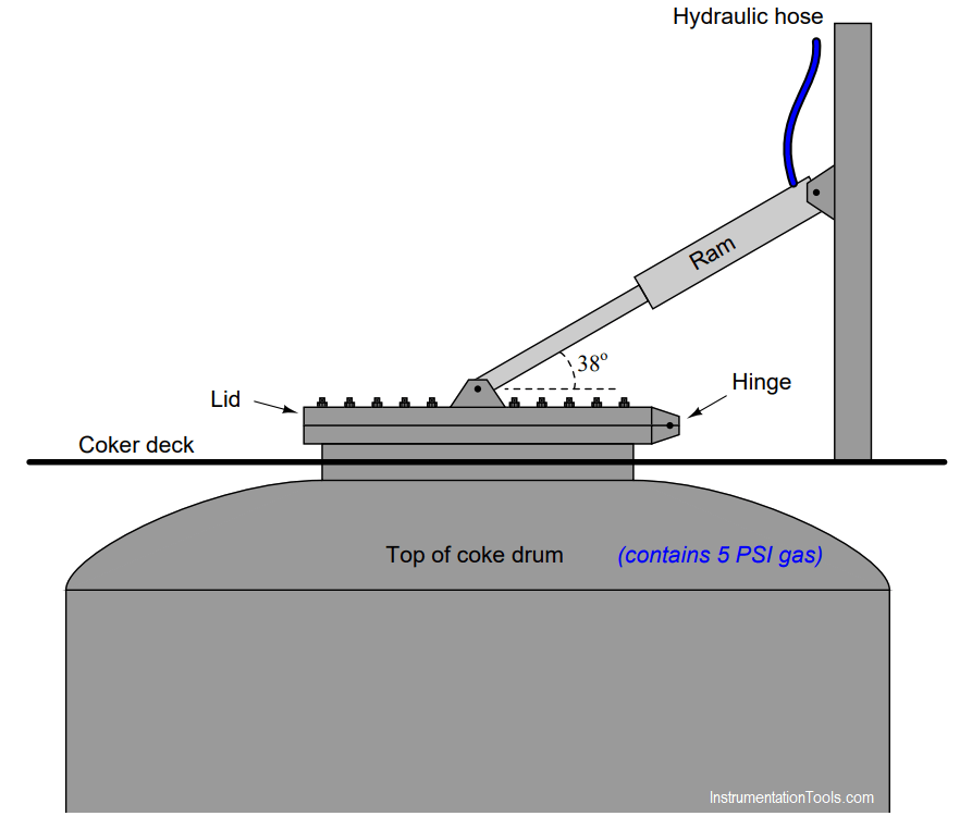
Calculate the hydraulic pressure necessary to hold down the lid on the coke drum when the gas pressure inside the drum is 5 PSI and all hold-down bolts have been removed from the lid. Assume a lid diameter of 30 inches, and a ram piston diameter of 4 inches.

Hint: sketch a right triangle, representing forces as side lengths on the triangle – the ram’s diagonal force will translate into both a horizontal force on the lid (which you may ignore) and a vertical force on the lid (which is what we’re interested in here).

Hydraulic P = __________ PSI

Solution:

With a piston diameter of 4 inches, a hydraulic pressure of 456.83 PSI is necessary to generate 5740.6 pounds.

This is a minimum pressure, for safety reasons.

More than 456.83 PSI won’t do any harm, but less than this amount will fail to hold down the lid!

More Questions:

1. Which direction will the horizontal force component be exerted on the lid?

2. Identify the potential hazards of a hydraulic oil leak in this system. Compare the effects of a slow leak (e.g. a leaky fitting connecting the hose to the ram) versus a catastrophic leak (e.g. the hose bursting from excess pressure).

Read Next:

  • Hydraulic Load Cell Principle
  • Drum Level Control System
  • Speed of Actuators
  • Fluid Power Systems
  • What is a Condensate Pot?

Credits: Tony R. Kuphaldt

Don't Miss Our Updates
Be the first to get exclusive content straight to your email.
We promise not to spam you. You can unsubscribe at any time.
Invalid email address
You've successfully subscribed !

Recommended Articles

Inspecting the Trends of PV and SP on a Process Chart Recorder
Motor Trip Logic using PLC Programming
Differential Capacitance Pressure Sensor Circuit
PLC Electric Motor Interlocks
Problem with Sump Tank Level Transmitter
Pressure Switch Questions
Share This Article
Facebook Whatsapp Whatsapp LinkedIn Copy Link
Share
Leave a Comment

Leave a Reply Cancel reply

Your email address will not be published. Required fields are marked *

Stay Connected

128.3kFollowersLike
69.1kFollowersFollow
208kSubscribersSubscribe
38kFollowersFollow

Categories

Recent Comments

  • William Snyder on Top Non-PLC Certification Courses for Automation Professionals
  • Kamli on Top Free PLC Software
  • Guifty Shimica on Top Non-PLC Certification Courses for Automation Professionals
  • Guifty Shimica on Top Non-PLC Certification Courses for Automation Professionals

Related Articles

Process Switches Normal Status

Define Normal Status for each of the Process Switch

Problem on Weigh feeder

Problem on Weigh feeder

Diagnosing the Electric Motor Circuit

Diagnosing Electric Motor Circuit

Air Compressor Control Circuit has a Problem

Air Compressor Control Circuit Problem

Siemens PLC Block Diagram

Programmable Logic Controller (PLC) Questions and Answers – 14

Allen-Bradley PLC Program

Troubleshoot Allen Bradley PLC Logic

Calculate LRV and URV for 4-20 mA Loop-powered DP Transmitter

Calculate LRV and URV for 4-20 mA Loop-powered DP Transmitter

DP Transmitter Located 10 feet Beneath the Vessel

DP Transmitter Located 10 feet Beneath the Vessel

More Articles

Nonlinear Control Systems

Construction of Phase -Trajectories

Single Block and Bleed Valve Manifold

Single Block and Bleed Valve Manifold Operation

Caliper Calibration

Setting Up for Success: Preparing for Caliper Calibration

positive displacement flow meter pictures

What is a Positive Displacement Flow Meter?

DP-Level-Transmitter-Diaphragm-with-capillary-tube-type

DP Level Transmitter Calibration for Diaphragm Seal with Capillary

How to Read an Electrical Wiring Diagram

How to Read an Electrical Wiring Diagram?

PLC Program to Control Motor Speed using VFD Drive

Motor Speed Control using VFD and PLC Programming

Gang Switch Principle

Reading Electrical Schematics

Follow US
All rights reserved. Reproduction in whole or in part without written permission is prohibited.
Welcome Back!

Sign in to your account

Username or Email Address
Password

Lost your password?