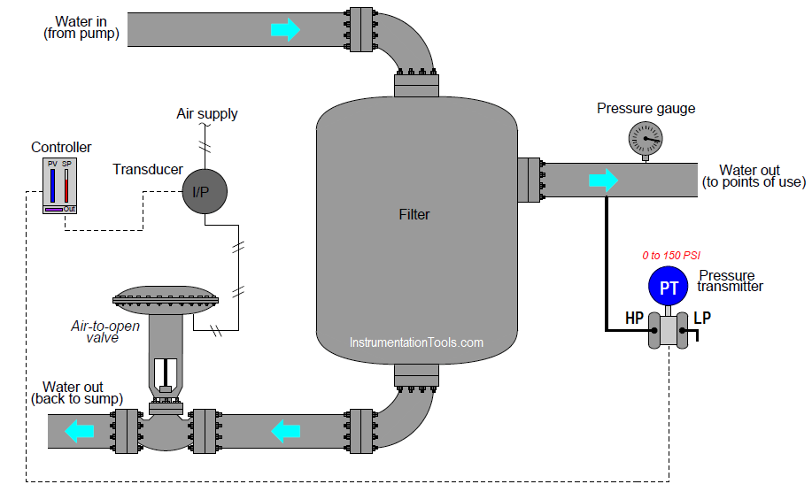
In this article, we are discussing an example problem on water filter discharge pressure transmitter and gauge, and these two readings are not matching.
This water filter’s discharge pressure is controlled by a PID controller, throttling the amount of water returned to the sump:

An operator tells you there is a problem with this system, though: the controller faceplate registers 146 PSI of water pressure, with a setpoint at 100 PSI. You happen to notice that the bargraph on the controller faceplate showing output is at 100%.
Another operator in the field (near the exchanger) reports via radio that the control valve stem is at the “closed” position, and that the pressure gauge mounted on the filter’s discharge line registers 143 PSI.
Another instrument technician happens to be with you, and recommends you connect a multimeter to the transmitter’s signal wiring to measure the 4-20 mA signal. Explain why this test would be a waste of time, and propose a better test for helping to pinpoint the location of the fault.
The reason that the technician’s proposed test would have been a waste of time is because the controller is already registering a reasonable pressure (approximately the same as the field-mounted gauge).
In other words, the controller PV indication corresponds with the gauge, suggesting there is no problem in that (input) portion of the control system.
How do you attend this issue in the field? Share with us through below comments section.
A valuable principle to apply in a diagnostic scenario such as this is correspondence: identifying which field variables correspond with their respective controller faceplate displays, and which do not. Apply this comparative test to the scenario described, and use it to explain why the technician’s proposed test was probably not the best first step.
Determine the proper action for this loop controller (direct or reverse).
Rotating equipment packages such as pumps, compressors, turbines need the lube oil consoles for their…
This article explains how to blink lights in ladder logic with a detailed explanation video…
In this article, a simple example will teach you the conversion from Boolean algebra to…
In this article, you will learn the PLC cooking timer example for kitchen automation using…
Learn an example PLC program to control a pump based on level sensors using ladder…
In the PLC timer application for security camera recording, when motion is detected then camera…