Inst ToolsInst ToolsInst Tools
  • Courses
  • Automation
    • PLC
    • Control System
    • Safety System
    • Communication
    • Fire & Gas System
  • Instrumentation
    • Design
    • Pressure
    • Temperature
    • Flow
    • Level
    • Vibration
    • Analyzer
    • Control Valve
    • Switch
    • Calibration
    • Erection & Commissioning
  • Interview
    • Instrumentation
    • Electrical
    • Electronics
    • Practical
  • Q&A
    • Instrumentation
    • Control System
    • Electrical
    • Electronics
    • Analog Electronics
    • Digital Electronics
    • Power Electronics
    • Microprocessor
  • Request
Search
  • Books
  • Software
  • Projects
  • Process
  • Tools
  • Basics
  • Formula
  • Power Plant
  • Root Cause Analysis
  • Electrical Basics
  • Animation
  • Standards
  • 4-20 mA Course
  • Siemens PLC Course
Reading: Problem on Water Filter Discharge Pressure Transmitter and Gauge
Share
Font ResizerAa
Inst ToolsInst Tools
Font ResizerAa
  • Courses
  • Design
  • PLC
  • Interview
  • Control System
Search
  • Courses
  • Automation
    • PLC
    • Control System
    • Safety System
    • Communication
    • Fire & Gas System
  • Instrumentation
    • Design
    • Pressure
    • Temperature
    • Flow
    • Level
    • Vibration
    • Analyzer
    • Control Valve
    • Switch
    • Calibration
    • Erection & Commissioning
  • Interview
    • Instrumentation
    • Electrical
    • Electronics
    • Practical
  • Q&A
    • Instrumentation
    • Control System
    • Electrical
    • Electronics
    • Analog Electronics
    • Digital Electronics
    • Power Electronics
    • Microprocessor
  • Request
Follow US
All rights reserved. Reproduction in whole or in part without written permission is prohibited.
Inst Tools > Blog > Pressure Measurement > Problem on Water Filter Discharge Pressure Transmitter and Gauge

Problem on Water Filter Discharge Pressure Transmitter and Gauge

Last updated: May 21, 2020 9:41 am
Editorial Staff
Pressure Measurement
No Comments
Share
3 Min Read
SHARE

In this article, we are discussing an example problem on water filter discharge pressure transmitter and gauge, and these two readings are not matching.

Water Filter Discharge Pressure

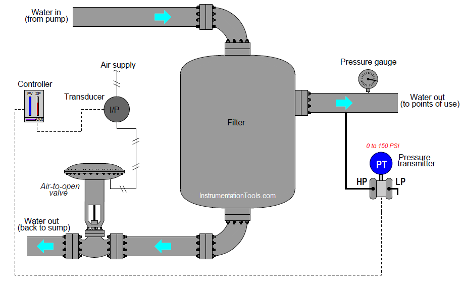
This water filter’s discharge pressure is controlled by a PID controller, throttling the amount of water returned to the sump:

Problem on Water Filter Discharge Pressure Transmitter and Gauge

An operator tells you there is a problem with this system, though: the controller faceplate registers 146 PSI of water pressure, with a setpoint at 100 PSI. You happen to notice that the bargraph on the controller faceplate showing output is at 100%.

Another operator in the field (near the exchanger) reports via radio that the control valve stem is at the “closed” position, and that the pressure gauge mounted on the filter’s discharge line registers 143 PSI.

Another instrument technician happens to be with you, and recommends you connect a multimeter to the transmitter’s signal wiring to measure the 4-20 mA signal. Explain why this test would be a waste of time, and propose a better test for helping to pinpoint the location of the fault.

Answer

The reason that the technician’s proposed test would have been a waste of time is because the controller is already registering a reasonable pressure (approximately the same as the field-mounted gauge).

In other words, the controller PV indication corresponds with the gauge, suggesting there is no problem in that (input) portion of the control system.

How do you attend this issue in the field? Share with us through below comments section.

Questions for you:

A valuable principle to apply in a diagnostic scenario such as this is correspondence: identifying which field variables correspond with their respective controller faceplate displays, and which do not. Apply this comparative test to the scenario described, and use it to explain why the technician’s proposed test was probably not the best first step.

Determine the proper action for this loop controller (direct or reverse).

Read Next:

  • Pressure Control Loop
  • What is a Condensate Pot?
  • Pressure Transmitter Circuit
  • Electrical and Instrumentation Test
  • Pressure Gauges Adjustment
Don't Miss Our Updates
Be the first to get exclusive content straight to your email.
We promise not to spam you. You can unsubscribe at any time.
Invalid email address
You've successfully subscribed !

Continue Reading

Components of Bourdon Tube – Questions and Answers
Pressure Gauge Selection
Capillary Tubing Pressure Sensor Temperature & Elevation Problems
Pressure Detection Circuit
Pressure Transmitters Purged impulse lines
Vacuum Gauges Working Principle
Share This Article
Facebook Whatsapp Whatsapp LinkedIn Copy Link
Share
Leave a Comment

Leave a Reply Cancel reply

Your email address will not be published. Required fields are marked *

Stay Connected

128.3kFollowersLike
69.1kFollowersFollow
210kSubscribersSubscribe
38kFollowersFollow

Categories

Explore More

What is LVDT ?
Pressure Gauges with Capsule Sensor Principle
Types of Bourdon Tube
Why are Impulse Lines often Installed in a Sloping Manner?
Resistance Type Pressure Transducers Principle
Troubleshooting Fluid Systems Pressure Changes
Differential Pressure Switch Principle
Differential Pressure Transmitter Working Principle

Keep Learning

Pressure Gauge Datasheet Preparation

How to Prepare Pressure Gauge Datasheet ?

How to Connect HART Communicator with DP Transmitter

15 HART Communicator Questions

Pressure Gauge Installation

Pressure Gauge Installation at Pump Discharge

Uncertainty Calculations of Pressure Calibration

Uncertainty Calculations of Pressure Calibration

Impulse Line Pressure Testing Procedure

Impulse Line Pressure Testing Procedure

Pressure Transmitter Impulse Lines Heat Trace

Pressure Transmitters Heat-traced impulse lines

Pressure Gauges Common Problems

Pressure Gauges : Common Causes for Failures and Their Effective Solutions

Pressure Unit Conversion Practical Example

Pressure Unit Conversion Practical Example

Learn More

pn-junction-energy-diagrams

Energy Diagrams of PN Junction & Depletion Region

Fieldbus Control Loop

Foundation Fieldbus Communication Management

Flow Measurement Objective Questions

Flow Measurement Objective Questions

Top Electrical Engineering Questions & Answers

Top Electrical Engineering Questions & Answers

Water Fountain Control Logic

Water Fountain Control Logic – PLC Exercises and Solutions

Nuisance Alarms

What is Alarm Shelving? – Nuisance Alarms, Types, Suppression

Slop Tank Level Transmitter Erection

Wrong Installation of Horn Type Radar Level Transmitter on Sloping Tank

Types of Sensors used in the Dairy Industry

Types of Sensors used in the Dairy Industry

Menu

  • About
  • Privacy Policy
  • Copyright

Quick Links

  • Learn PLC
  • Helping Hand
  • Part Time Job

YouTube Subscribe

Follow US
All rights reserved. Reproduction in whole or in part without written permission is prohibited.
Welcome Back!

Sign in to your account

Username or Email Address
Password

Lost your password?