Shown here is a very simple pressure transmitter, a device that measures a fluid pressure and converts that measurement into an electrical signal:
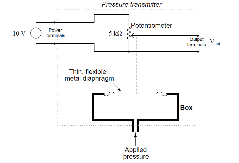
Suppose the potentiometer wiper will be at its full-down position with no pressure applied to the diaphragm, and will be at its full-up position with 15 PSI (15 pounds per square inch) of pressure applied to the diaphragm.
Based on this information, and what you see in the schematic diagram, answer the following questions:
Now, suppose we make a modification to the electrical circuit portion of the pressure transmitter. Assume the diaphragm still responds to pressure and moves the potentiometer wiper the same way it did before. Answer the same questions again:
The latter design outputs what is commonly called a live-zero signal, whereas the first transmitter outputs a dead-zero signal. Live-zero signals are much preferred in industrial instrumentation, because they more readily betray wiring failures than dead-zero signals.
Explain how you answered all the questions, and also show currents and voltage drops in both circuits (complete with arrows showing directions of current). Then, elaborate on why you think live-zero signals are preferable to dead-zero signals.
First transmitter design:
Last transmitter design:
Share your answers with us through below comments section.
Credits: Tony R. Kuphaldt
PLC ladder logic design to control 3 motors with toggle switch and explain the program…
VFD simulator download: Master the online tool from the Yaskawa V1000 & programming software for…
The conveyor sorting machine is widely used in the packing industries using the PLC program…
Learn the example of flip-flop PLC program for lamps application using the ladder logic to…
In this article, you will learn the STAR DELTA programming using PLC controller to start…
Lube oil consoles of rotary equipment packages in industrial process plants are usually equipped with…

