In Today’s automation world, Pneumatic system plays an important role in delivering consistent and efficient motion control solutions. Likewise, the given system is the application of an electro-pneumatic circuit operated through the interaction of a sensor control mechanism. The circuit is designed in such a case when the push button is pressed, the cylinder starts to move in the forward direction after getting the signal from the Proximity sensor. Once the cylinder reaches the end position, it will sense the second proximity sensor, which will make the cylinder move in reverse, and it will move to its home position.
Again, it will make sense for the first sensor and move forward. It will create a cycle of extension and retraction of the cylinder. This Cycle will stop by pressing the stop button manually. This system combines mechanical motion with sensor sensing, making it a semi-automatic process, which makes the system efficient and reduces human work. Because of the sensor, we will get the precise signal, which shows the fundamentals of the automation system in the modern world. These kinds of circuits will be used in the application of material handling, assembly lines, and packing, where repetitive action is required more.
Components
- Double Acting Cylinder
- 5/2 Solenoid Actuated Directional Control Valve
- Flow Control Valve
- Start & Stop Buttons
- Relay Coil
- Proximity Sensors
- Solenoid Valves
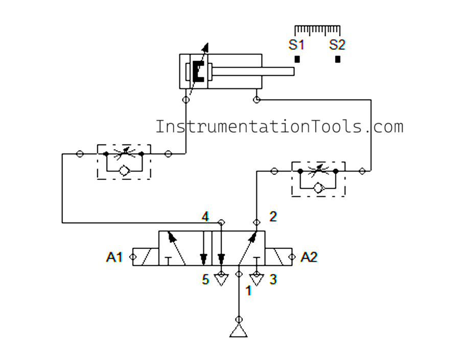
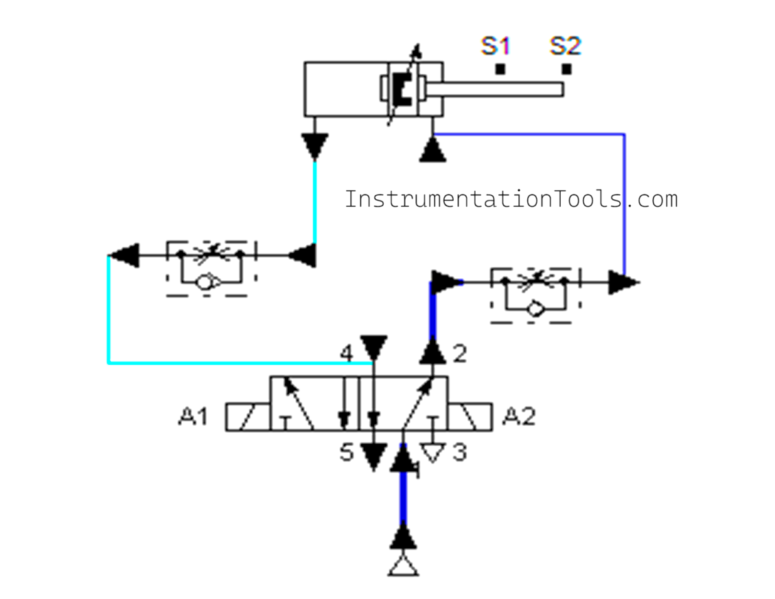
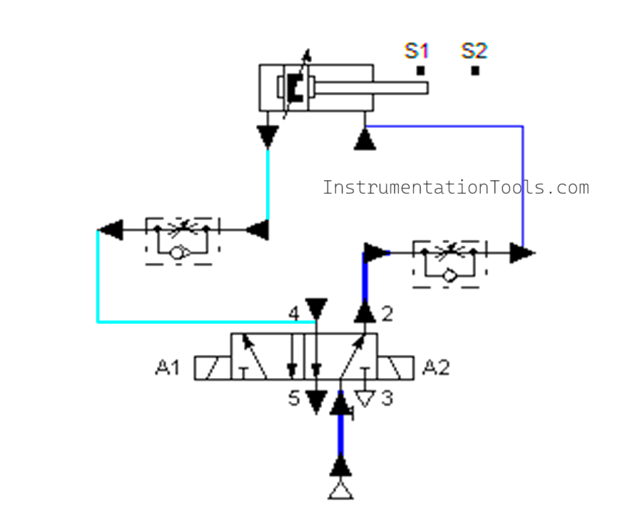
Pneumatic Circuit
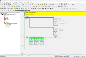
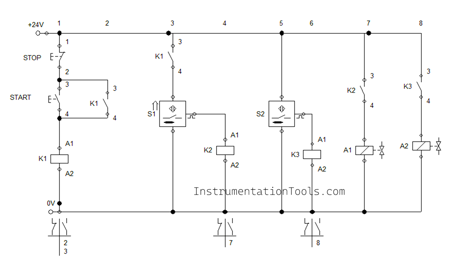
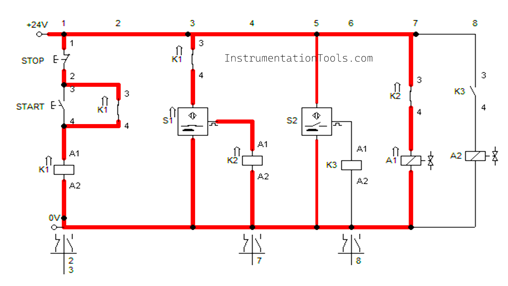
Control Circuit
Simulation Video
Watch the video simulation below of the pneumatic cylinder motion control.
Pneumatic Cylinder To and Fro Motion Control Operation
Air supply is given to the circuit through the Compressor. And the Cylinder was initially in the home rest position.
In the control circuit, 24 V DC supply was given to the system. Push Buttons, Relay coils, Solenoid Coils, and Proximity sensors were connected in the control circuit.
Proximity Sensor S1 was connected to the home position of the Cylinder piston.
The start push button was pressed, which made the Relay K1 activate. Then the Relay contact K1 was closed, and previously itself proximity sensor S1 was in contact with the cylinder. So these two contacts make the Relay K2 activate.
Activation of Relay K2 causes the contact of K2 to close, which activates the solenoid A1. Activation of Solenoid A1 makes the cylinder move forward.
Proximity Sensor S2 was placed at the cylinder’s end position. During the activation of Solenoid A1, the cylinder moves forward and makes contact with Proximity sensor S2.
Contact of Proximity Sensor S2 makes relay K3 activate, then the activation of relay K3 makes the contact of K3 close, which activates the solenoid A2. Activation of solenoid A2 causes the cylinder to move backward.
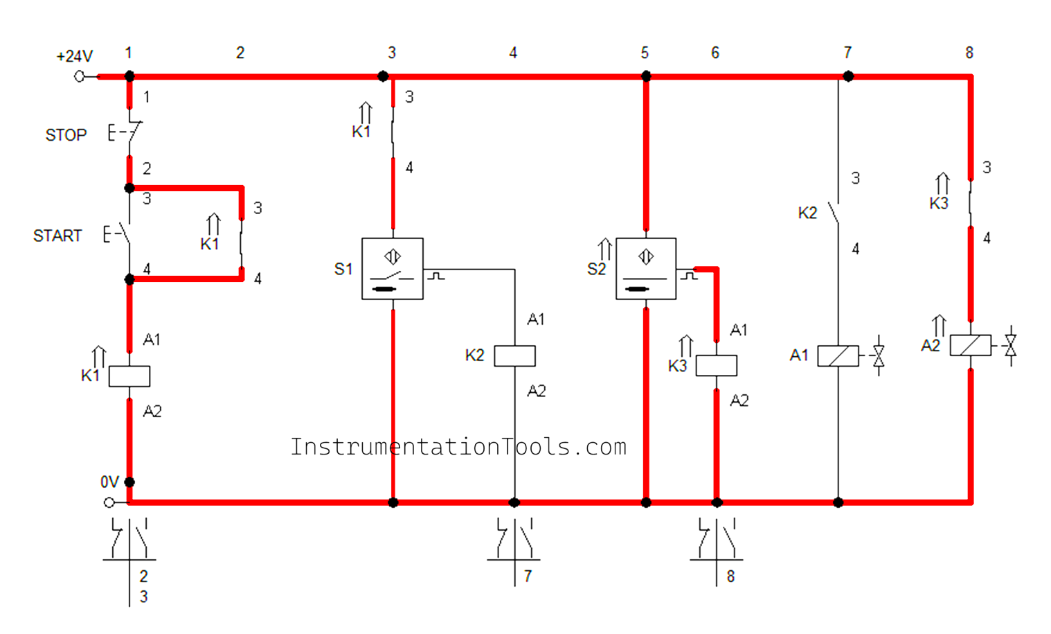
While retracting the cylinder will make contact with the Proximity sensor S1, which will activate the solenoid A1, which makes the cylinder move forward. And again, it will make contact with Proximity Sensor S2, which will activate the solenoid A2, which makes the cylinder move backward.
This process will repeat until the Stop push button is pressed. Again, if we press the Start button, the process will continue.
Flow control was used here to control the speed of the piston.
This type of Pneumatic operation was mainly used in repeated tasks like assembly, packing, and pressing processes.
Conclusion
In summary, the given pneumatic is an effective method of achieving the automatic reciprocating motion of the cylinder with the semi-automatic process by integrating the Push buttons and proximity sensors. The cylinders’ forward and reverse strokes were easily managed by the sensors, which makes the repeated motion suitable for the industrial automation systems. Likewise, it also reduces the manual efforts and increases the productivity with accuracy and as well as safety. Overall, this pneumatic circuit shows how the Pneumatic elements can integrate with sensors for effective, reliable, cost–effective, and safe solutions for different automated processes in today’s industrial automation world.
Read Next:
- Pneumatic Cylinder Control Circuit using Timers
- Control of Pneumatic Cylinder and Motor Explained
- PLC Control of Double-acting Pneumatic Cylinder
- Sequential PLC Program Pneumatic Valve
- Speed Control of Pneumatic Cylinder Explanation