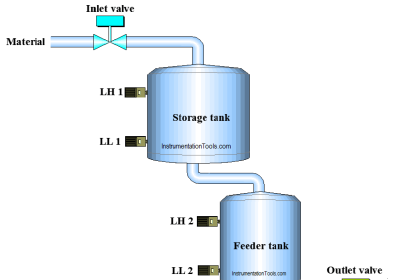
This article discusses the “Loss in Weight Liquid” system using Schneider PLC Ecostruxure Machine Expert-Basic Software. This PLC system has a tank for storing liquids and a tank for measuring liquids. The liquid storage tank will always be filled with liquid with a capacity of 150 liters and this system can only be started if the minimum liquid content parameter for the storage tank has been set.
The liquid measuring tank will only be filled with liquid when it gets a Trigger. The liquid measuring tank has a maximum liquid content limit parameter that can be set and when the measuring tank is filled with liquid according to the value in the parameter, the liquid will flow out (Drain Process).
Loss in Weight Liquid Systems
The PLC program Buttons used are listed below.
- The PB_START (I0.0) button is used to turn ON the system.
- The PB_STOP (I0.1) button is used to turn OFF the system.
- The START_FILL (I0.2) button is used to Start the filling process in the Dosing Tank.
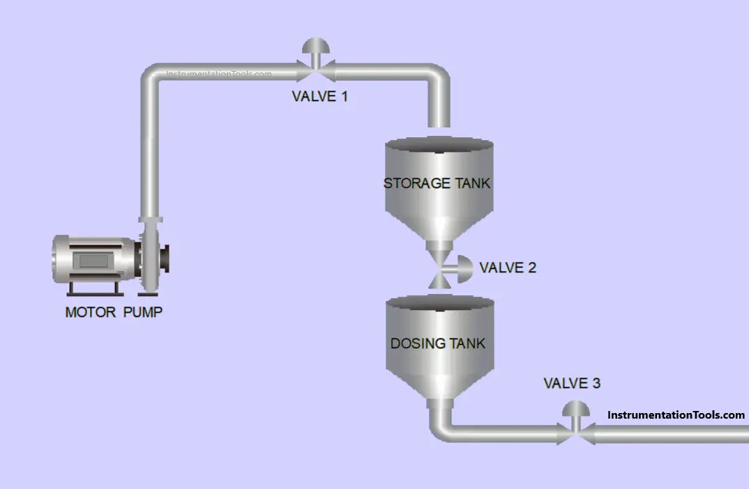
Tank Storage Filling
Filling the Storage Tank will be carried out if the liquid content of the Storage Tank is below the Minimum limit.
Valve 1 will OPEN first, the Motor Pump will turn ON 2 seconds later to fill liquid into the Storage Tank.
The Motor Pump will turn OFF and Valve 1 will CLOSE when the liquid content has reached the Maximum tank limit (150 liters).
Filling Dosing Tank
Before the Dosing Tank filling process is carried out, the “Set value” parameter for the liquid content of the Dosing Tank must be Set and the Dosing Tank filling process will begin.
If the START_FILL (I0.2) button is Pressed, Valve 2 will OPEN to drain the liquid from the Storage Tank to the Dosing Tank. Valve 2 will CLOSE when the Dosing Tank has been filled with liquid according to the “Set value” parameter.
2 Seconds later, Valve 3 will OPEN to drain the liquid contents from the Dosing Tank. Valve 3 will CLOSE again when the Dosing Tank is empty.
Program Addresses
| Comment | Input (I) | Output (Q) | Memory Word | Memory Bits | Timer |
| PB_START | I0.0 | ||||
| PB_STOP | I0.1 | ||||
| START_FILL | I0.2 | ||||
| VALVE_1 | Q0.0 | ||||
| VALVE_2 | Q0.1 | ||||
| VALVE_3 | Q0.2 | ||||
| MOTOR_PUMP | Q0.3 | ||||
| TIMER_1 | TM0 | ||||
| TIMER_2 | TM1 | ||||
| SYSTEM_ON | M0 | ||||
| IR_CUTOFF1 | M1 | ||||
| IR_CUTOFF2 | M2 | ||||
| IR_VALVE3 | M3 | ||||
| IR_TIMER1 | M4 | ||||
| IR_TIMER2 | M5 | ||||
| SV_TANK1 | MW0 | ||||
| PV_TANK1 | MW1 | ||||
| SV_TANK2 | MW2 | ||||
| PV_TANK2 | MW3 |
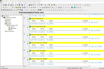
PLC Program
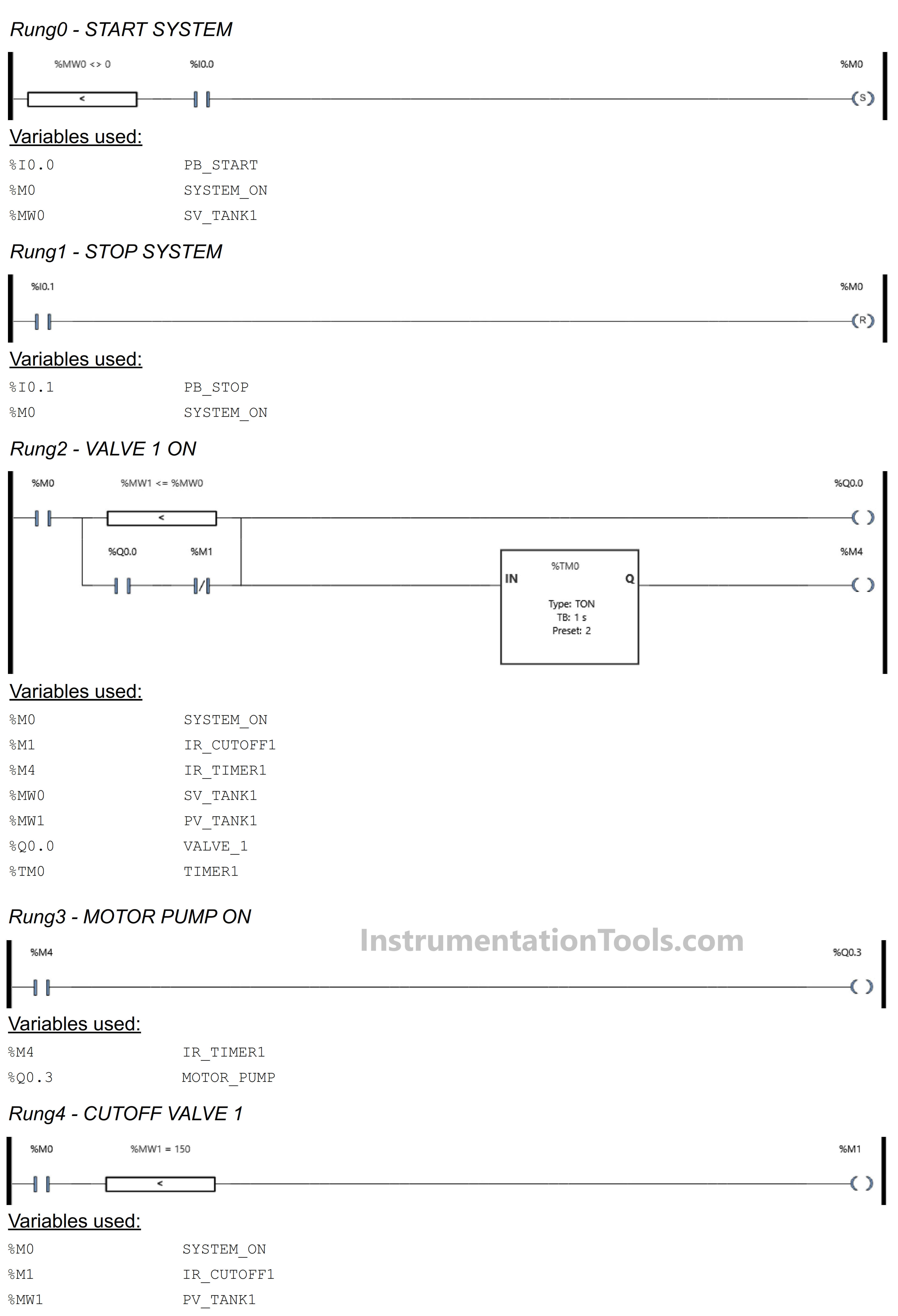
RUNG 0 (START SYSTEM)
In this Rung, the memory bit SYSTEM_ON (M0) will be in the HIGH state if the memory word SV_TANK1(MW0) has a value not equal to zero “0” and the PB_START (I0.0) button is Pressed.
The memory bit SYSTEM_ON (M0) remains in the HIGH state even though the PB_START (I0.0) button has been Released, because it uses the SET Coil Instruction.
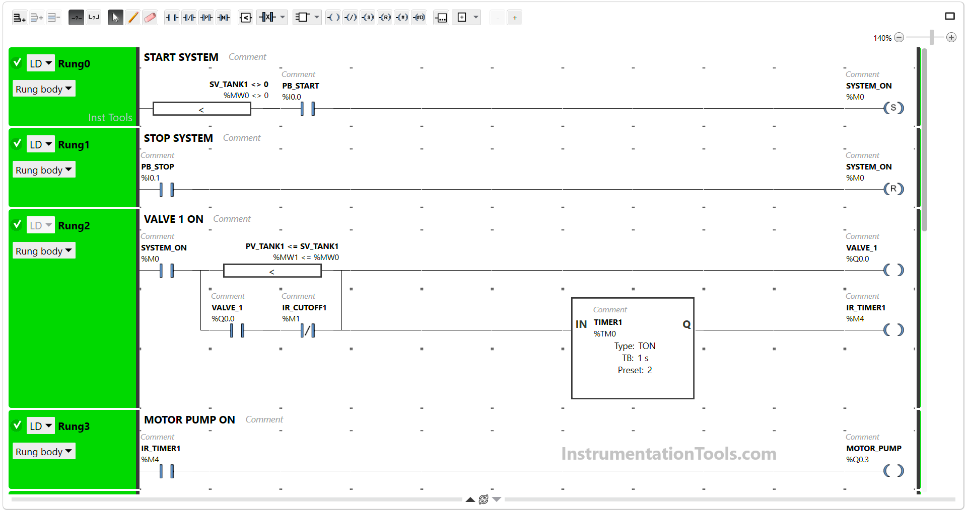
RUNG 1 (STOP SYSTEM)
In this Rung, if the PB_STOP (I0.1) button is Pressed, the memory bit SYSTEM_ON (M0) will become LOW state. Because it uses the RESET Coil Instruction.
RUNG 2 (VALVE 1 ON)
In this Rung, the Output VALVE_1 (Q0.0) will be ON when the NO contact of memory bit SYSTEM_ON (M0) in the HIGH state and the value in the memory word PV_TANK1 (MW1) is Less Than Or Equal to SV_TANK1 (MW0).
The TIMER_1 (TM0) timer starts counting up to 2 seconds and after it has finished counting, the memory bit IR_TIMER1 (M4) will be in the HIGH state.
RUNG 3 (PUMP MOTOR ON)
The MOTOR_PUMP (Q0.3) Output will be ON if the NO contact of memory bit IR_TIMER1(M4) in the HIGH state.
RUNG 4 (CUTOFF VALVE 1)
In this Rung, the memory bit IR_CUTOFF1 (M1) will be in the HIGH state if the NO contact of memory bit SYSTEM_ON (M0) in the HIGH state and the value in the memory word PV_TANK1 (MW1) is Equal to “150”.
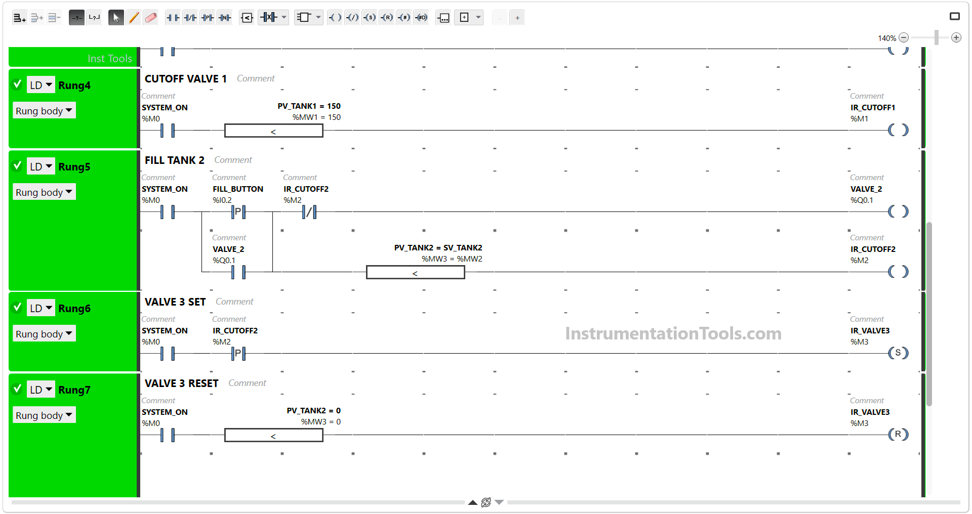
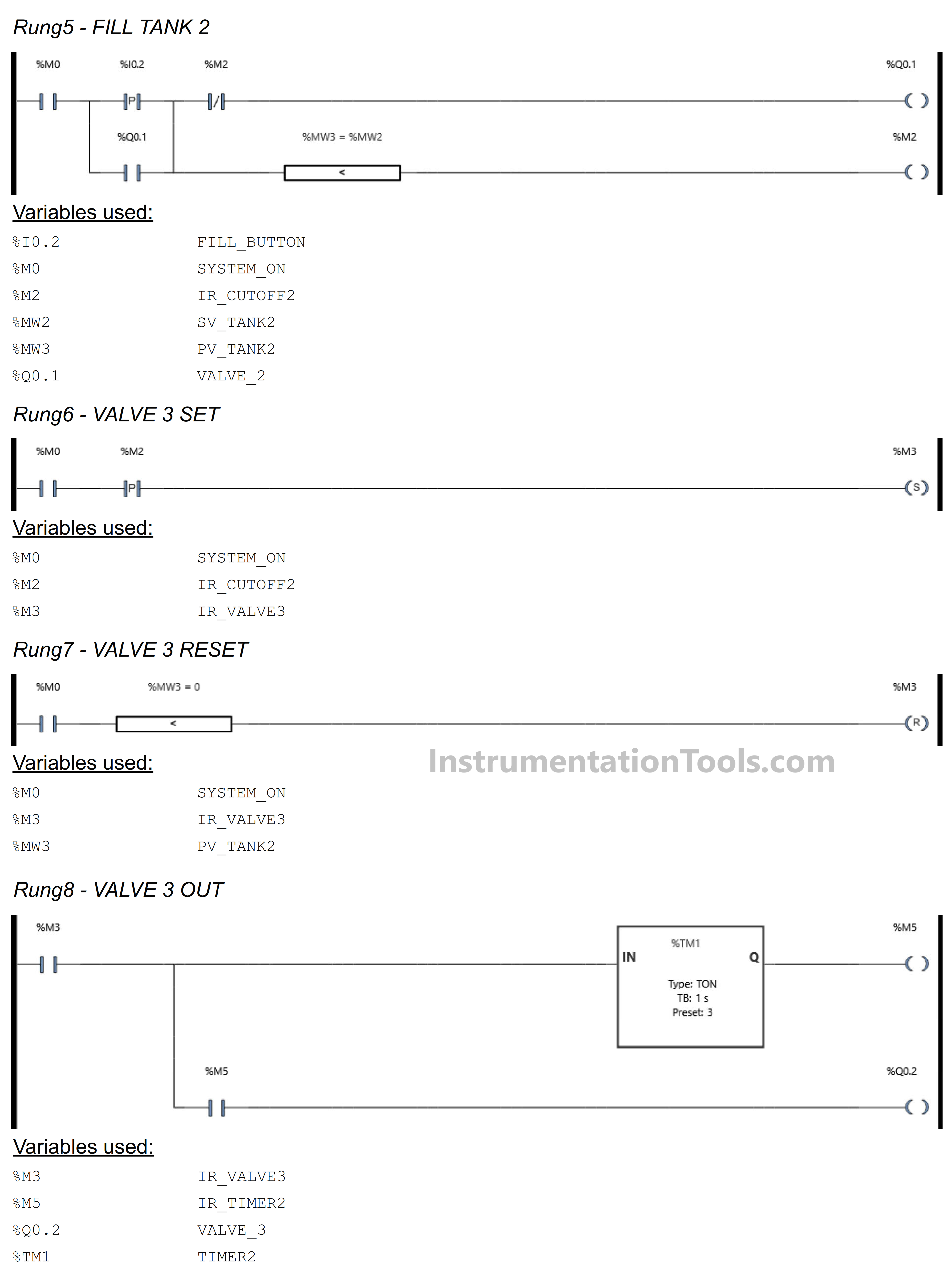
RUNG 5 (FILL TANK2)
In this Rung, Output VALVE_2 (Q0.1) will be OPEN if the NO contact of memory bit SYSTEM_ON (M0) in the HIGH state and the START_FILL (I0.2) button is Pressed. Because it uses Latching, Output VALVE_2 (Q0.1) will remain OPEN even though the START_FILL (I0.2) button has been Released.
If the value of memory word PV_TANK2 (MW3) is Equal to SV_TANK2 (MW2), then the memory bit IR_CUTOFF2 (M2) will be in the HIGH state and the Output VALVE_2 (Q0.1) will be CLOSE because of the Interlock.
RUNG 6 (VALVE 3 SET)
In this Rung, the memory bit IR_VALVE3 (M3) will be in HIGH state if the NO contacts of memory bits SYSTEM_ON (M0) and IR_CUTOFF2 (M2) are in HIGH state. Because it uses the SET Coil Instruction, the memory bit IR_VALVE3 (M3) remains in HIGH state even though the NO contacts of memory bit IR_CUTOFF2 (M2) are in LOW state.
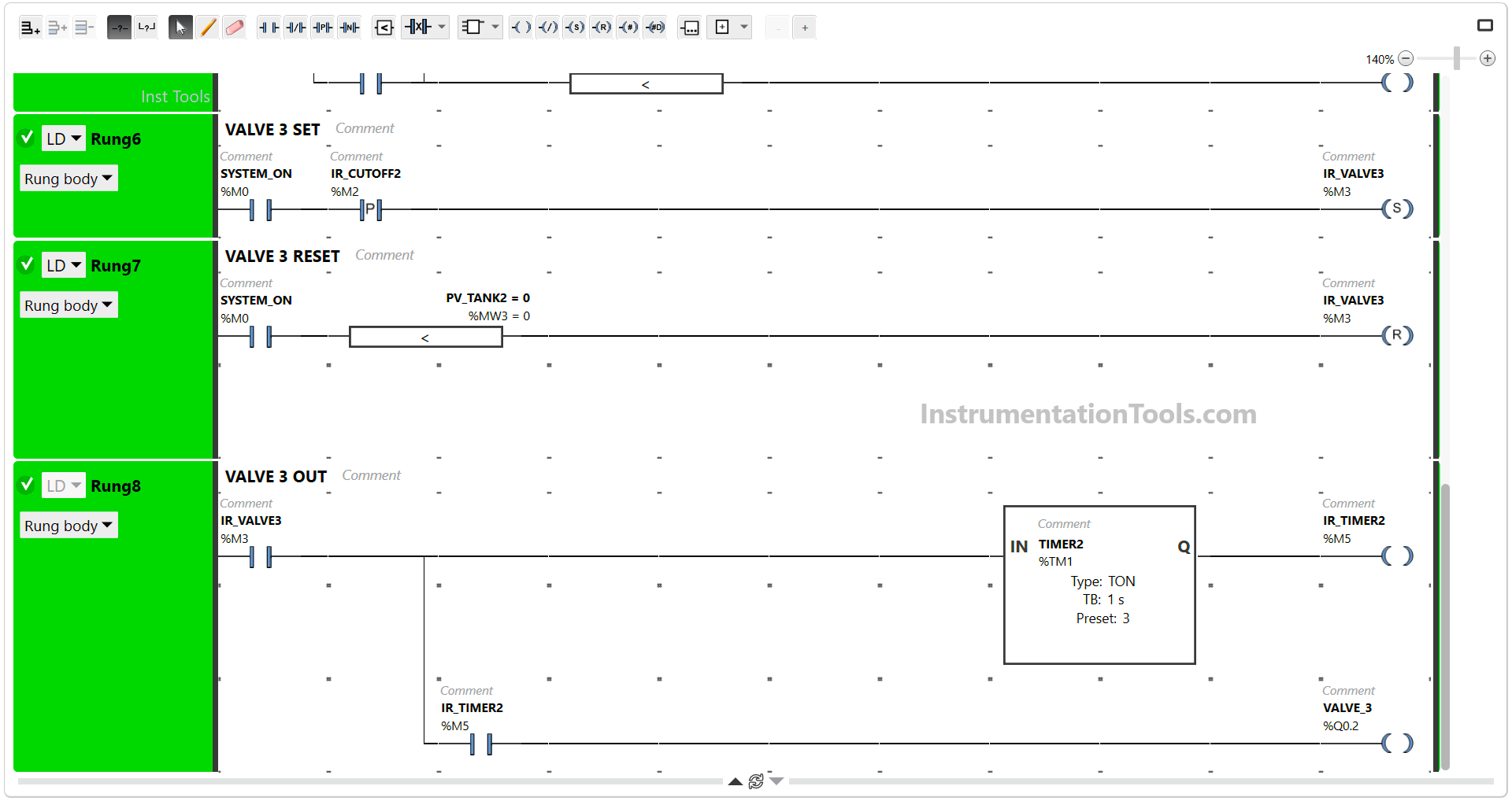
RUNG 7 (VALVE 3 RESET)
If the value in the memory word PV_TANK2 (MW3) is zero “0”, then the memory bit IR_VALVE3 (M3) will be in the LOW state. Because it uses the RESET Coil Instruction.
RUNG 8 (VALVE 3 OUT)
In this Rung, Timer TIMER_2 (TM1) will Start counting up to 3 seconds if the NO contact of memory bit IR_VALVE3 (M3) in the HIGH state. When Timer TIMER_2 (TM1) has finished counting, the memory bit IR_TIMER2 (M5) will be in HIGH state and Output VALVE_3 (Q0.2) will be ON.
If the NO contact of IR_VALVE3 (M3) memory bit in the LOW state, then the VALVE_3 (Q0.2) Output will be OFF.
Read Next:
- How to Program PID Control in PLC with STL?
- AB PLC Motor Running Hours Programming
- STAR-DELTA Auto And Manual Programming
- PLC Programming for Baking with Auto Mode
- PLC Programming for Train Detection System