Make the example ladder logic to control the motor in forward and reverse direction using PLC Programming with limit switches as sensors.
PLC Example for Motor
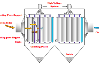
The Workpiece starts moving on the left side and moves to the right when the start button is pressed.
When it reaches the rightmost limit, the drive motor reverses and brings the workpiece back to the leftmost position again and the process repeats.
The forward and reverse pushbuttons provides a means of starting the motor in either forward or reverse so that the limit switches can take over automatic control.
Motor Forward and Reverse Control

List of Inputs and Outputs

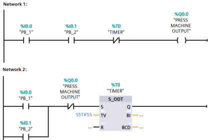
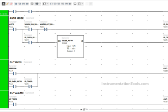
PLC Program

Program Description
RUNG 0000
Latching rung to operate the system through Master Start and Stop PB.
RUNG 0001
When the workpiece is near Limit switch1, It will enable forward motor, for latching forward Motor is connected in parallel with limit switch 1.
Forward Pushbutton (PB) is also connected in parallel to manually operate forward motor.
RUNG 0002
When the workpiece is near Limit switch2, It will enable reverse motor, for latching reverse Motor is connected in parallel with limit switch 2.
Reverse Pushbutton (PB) is also connected in parallel to manually operate Reverse motor.
Conclusion:
The above-explained process is for example only. It may vary from real-time.
If you liked this article, then please subscribe to our YouTube Channel for PLC and SCADA video tutorials.
You can also follow us on Facebook and Twitter to receive daily updates.
Read Next:
JUMP Instruction in PLC Program


write a ladder logic when start switch on a lamp glow continuously. but the same switch is turn on the same lamp blinks on and off.
How to program this
why fwd & rev motor latched
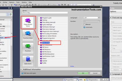
I tried to apply this on TIA PORTAL
CPU : 314C .
HMI: TP 700 Comfort.
The CPU SIM works normally with no problem.
The HMI SIM : It seems to me like there no link between the HMI and the CPU, I made a START button that activates the START input but it’s not working. Knowing that I did the connection between both cpu and hmi.
What could be the problem, plz ?