This is a PLC Program to drain the same products from two tanks. Learn the PLC programming with this simple example.
Problem Description
Two tanks are filled with same products. Draining materials from these two tanks is depended on the requirement of storage tank.
Implement logic for this system in PLC using ladder diagram.
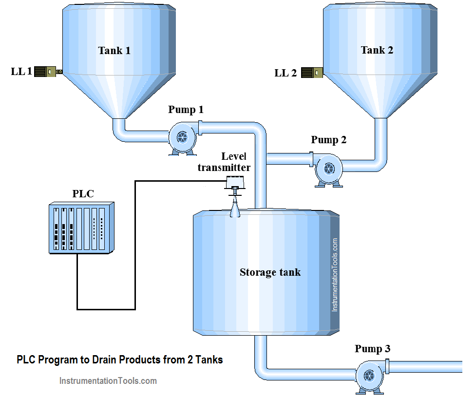
Here two tanks are used for the system. For level measurement, two sensors are used (level low sensors). As shown in figure we use here two pumps for transferring the materials from tanks (Tank 1 & Tank 2) to storage tanks.
Here we will use level transmitter for storage tank level measurement. PUMP 1 & PUMP 2 will be controlled by level transmitter feedback.
Here we used two pumps for smooth operation. Both pumps will be operated when level of the storage tanks is detected below its limit.
Note:-Here we are consider simple automation for this system. Level transmitter is used in this system and it will measure the level of the storage.
Storage tank is taken of 500cm height for simplicity and level transmitter feedback is 4 to 20mA.
We will use PLC S7-300 for this application. We will use scaling for programming purpose.
For this application, we used S7-300 PLC and TIA portal software for programming.
we used latching circuit for cycle ON (M0.0) output.it can be started by pressing START PB (I0.0) and stop by pressing STOP PB (I0.1).
Here actual count or value coming from the transmitter is current (4 to 20mA) so by using analog input channel in the PLC we can convert it into digital count. This digit is in INT (MW10) format so we need to convert it into DINT (MD100) for calculation or multiplication.
DINT value (MD100) is multiplied with max height (500cm) of the tank for calculation purpose.
Multiplied value (MD104) is divided by max count of the analog module (27648).And final actual height is stored in MD108.
Here we used comparator for PUMP 1 (Q0.0).During requirement of the material PUMP 3 will be operated by operator, water level height will decrease.
So as per our automation or system we need to fill storage tank, pump 1 will be started if water level is less than its limit (here we have taken 480cm).
Note:- PUMP 1 should be stop if level low (I0.2) of the tank 1 is detected.
Here we used comparator for PUMP 2 (Q0.1). During requirement of the material PUMP 3 will be operated by operator, water level height will decrease. So as per our automation or system we need to fill storage tank, pump 2 will be started if water level is less than its limit (here we have taken 480cm).
Note:- PUMP 2 should be stop if level low (I0.3) of the tank 2 is detected.
During all function cycle should be ON.
Note:- Above application may be different from actual application. This example is only for explanation purpose only. We can implement this logic in other PLC also. This is the simple concept of drainage system, we can use this concept in other examples also.
All parameters considered in example are for explanation purpose only, parameters may be different in actual applications. Also all interlocks are not considered in the application.
If you liked this article, then please subscribe to our YouTube Channel for PLC and SCADA video tutorials.
You can also follow us on Facebook and Twitter to receive daily updates.
Read Next:
VFD simulator download: Master the online tool from the Yaskawa V1000 & programming software for…
The conveyor sorting machine is widely used in the packing industries using the PLC program…
Learn the example of flip-flop PLC program for lamps application using the ladder logic to…
In this article, you will learn the STAR DELTA programming using PLC controller to start…
Lube oil consoles of rotary equipment packages in industrial process plants are usually equipped with…
Rotating equipment packages such as pumps, compressors, turbines need the lube oil consoles for their…


