By using AC Drive and Closed-Loop Control Program in PLC, we have to control output gas pressure as per setpoint given in SCADA. Implement this program in PLC using Ladder Logic programming language.
PLC Program to Control Gas Pressure

Problem Solution:
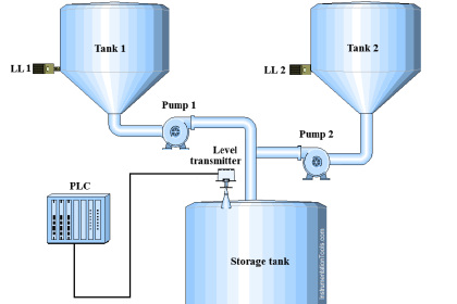
- To measure gas pressure, Pressure transmitter installed at input as well as output gas pipe line.
- Range of pressure transmitter is 0-20kPa.
- Output of this transmitter is in standard electrical signal which is 4-20 mA. Convert this signal into digital signal by connecting level transmitter to AI module of PLC.
- Blower fan motor is controlled by AC Drive, so we can control the speed of the motor.
- We can collect the motor rpm feedback and also give the set point to increase or decrease the speed of the motor as per output pressure transmitter feedback using PLC Program.
- Motor speed feedback from AC Drive and Set point of Speed to AC Drive is in standard electrical signal 4-20 mA. Convert this signal into digital signal by connecting feedback to PLC AI module and set point from PLC AO module to AC Drive.
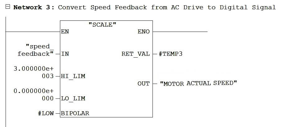
- Range of Motor Speed is 3000 RPM.
- Prepare a proper Closed-loop control logic to control output gas pressure.
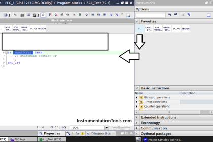
PLC Program:
The below table shows different types of inputs and outputs used in the ladder logic.

Here is the PLC program to control output gas pressure as per setpoint given in SCADA.

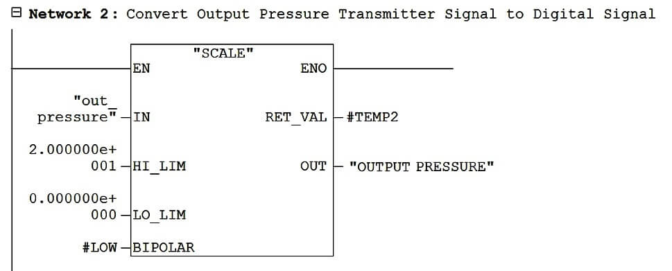
In the first three network, From Network 1 to Network 2 we are converting field signal 4-20 mA into digital signal (0–20 kPa), This is to show actual pressure in SCADA.
And in Network 3 is the conversion of Blower fan motor actual speed which is in 0-3000 rpm.
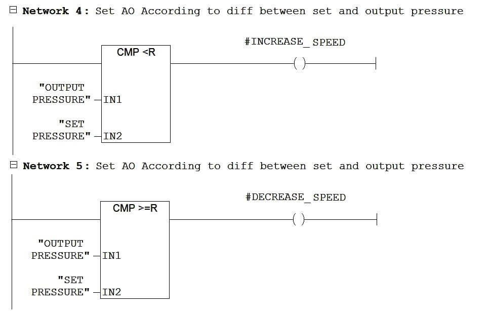
Network 4 and 5 does the comparison of Set Pressure, which is given from SCADA, and Output pipe line gas pressure. Based on this comparison it will give output to increase or decrease motor speed.
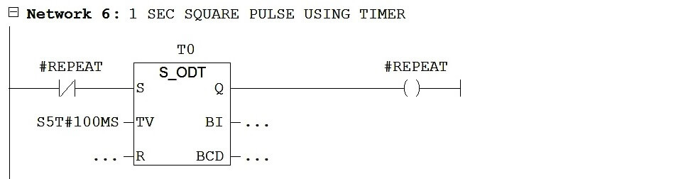
This Network 6 is the 1 sec square wave which we will use to increase or decrease the speed of motor by 100 rpm at every 1 sec.
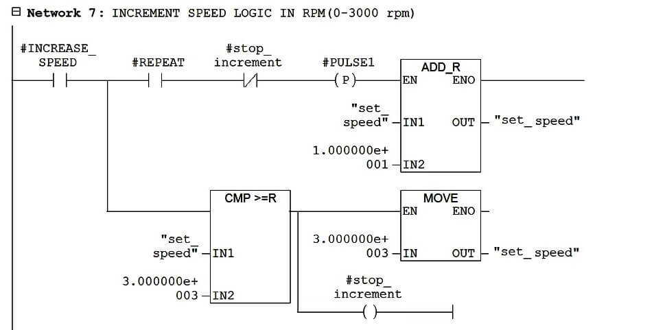
In this Network 7, we are doing the increment in speed of blower fan motor by 100 rpm at every 1 sec only if INCREASE_SPEED bit is high that means output pipe line pressure is low than Set Pressure in SCADA.
If the increment goes beyond the 3000 rpm then it will transfer the 3000 value to set_speed and stop incrementing further.
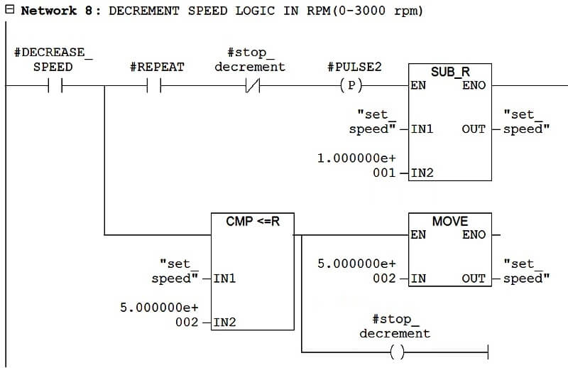
In this Network 8, we are doing the decrement in speed of blower fan motor by 100 rpm at every 1 sec only if DECREASE_SPEED bit is high that means output pipe line pressure is higher than Set Pressure in SCADA.
If the decrement goes below the 500 rpm then it will transfer the 500 value to set_speed and stop decrementing further.
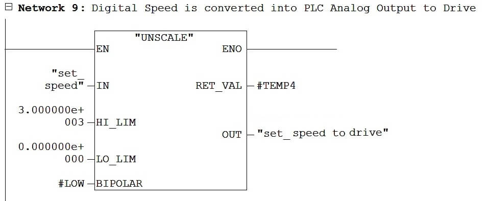
And lastly in this Network 9, we are converting digital speed into Analog Signal 4-20 mA. Then this signal is given to AC Drive to control the speed of blower fan motor.
If you liked this article, then please subscribe to our YouTube Channel for PLC and SCADA video tutorials.
You can also follow us on Facebook and Twitter to receive daily updates.
Read Next:
Troubleshoot Allen Bradley PLC


Can anyone help me to know that what is that no. In hi limit and low limit like3.000000e and 003 in some rung????
That is the high limit and low limit values in which you want to convert your analog output.
Like for the unscale in Network 9, High limit value is 3000 and low limit value is 0. Now when you want to set your speed at 50% or 1500 rpm then your output should be at 50% or in terms of electrical signal(4 to 20 mA) we can say that it should be 12mA. So that VFD can understant that it have to set RPM at 50% or 1500 rpm.
Hello there,Sir what kind of communication used in this example ,how ac drive communicate to the plc i hope you reply thanks,
And also sir ,how you get the set speed feedback Piw260 in network 3 how is that