By using this site, you agree to the Privacy Policy and Terms of Use.
Accept
Inst ToolsInst ToolsInst Tools
  • Ask
  • Courses
  • Videos
  • Q & A
    • Interview
      • Instrumentation
      • Electronics
      • Electrical
      • Practical Questions
    • MCQ
      • Instrumentation MCQ
      • Electrical MCQ
      • Electronics MCQ
      • Control Systems MCQ
      • Analog Electronics MCQ
      • Digital Electronics MCQ
      • Power Electronics MCQ
      • Microprocessor MCQ
      • Multiple Choice Questions
  • EE
    • Electronics
      • Electronics Q & A
      • Electronic Basics
      • Electronic Devices & Circuits
      • Electronics Animation
      • Digital Electronics
    • Electrical
      • Electrical Basics
      • Electrical Q & A
      • Power Electronics
      • Electrical Machines
      • Electrical Animation
      • Power Systems
      • Switchgear & Protection
      • Transmission & Distribution
  • Measure
    • Control Valves
    • Calibration
    • Temperature
    • Pressure
    • Flow
    • Level
    • Analyzers
    • Switches
    • Vibration
    • Solenoid Valve
  • Control
    • PLC Tutorials
    • Control Systems
    • Safety Instrumented System (SIS)
    • Communication
    • Fire & Gas System
  • More
    • Design
    • Tools
    • Animation
    • Basics
    • Formulas
    • Standards
    • TextBooks
    • Common
    • Software
    • Excel Tools
    • Erection & Commissioning
    • Process Fundamentals
    • Videos
    • Books
Search
All rights reserved. Reproduction in whole or in part without written permission is prohibited.
Reading: Example PLC Program to Control a Pump based on Level Sensors
Share
Notification Show More
Font ResizerAa
Inst ToolsInst Tools
Font ResizerAa
  • Ask
  • Courses
  • Videos
  • Q & A
  • EE
  • Measure
  • Control
  • More
Search
  • Ask
  • Courses
  • Videos
  • Q & A
    • Interview
    • MCQ
  • EE
    • Electronics
    • Electrical
  • Measure
    • Control Valves
    • Calibration
    • Temperature
    • Pressure
    • Flow
    • Level
    • Analyzers
    • Switches
    • Vibration
    • Solenoid Valve
  • Control
    • PLC Tutorials
    • Control Systems
    • Safety Instrumented System (SIS)
    • Communication
    • Fire & Gas System
  • More
    • Design
    • Tools
    • Animation
    • Basics
    • Formulas
    • Standards
    • TextBooks
    • Common
    • Software
    • Excel Tools
    • Erection & Commissioning
    • Process Fundamentals
    • Videos
    • Books
Follow US
All rights reserved. Reproduction in whole or in part without written permission is prohibited.
Inst Tools > Blog > PLC Tutorials > Example PLC Program to Control a Pump based on Level Sensors

Example PLC Program to Control a Pump based on Level Sensors

Learn an example PLC program to control a pump based on level sensors using ladder diagram logic with a video explanation.

Last updated: April 10, 2024 11:15 am
Editorial Staff
PLC Tutorials
No Comments
Share
4 Min Read
SHARE

Learn an example PLC program to control a pump based on level sensors using ladder diagram logic with a video explanation.

Contents
PLC Program to Control a PumpPLC Learning SeriesInputsOutputsLadder Diagram LogicProgram DescriptionTest Case

Note: The PLC logic example is designed for beginners who are interested to learn the ladder diagrams.

PLC Program to Control a Pump

Problem Statement

Design a PLC ladder logic for the following application.

We are using two level sensors to control the pump. (You can also call them as Level switches in this case).

If the low-level sensor detects the tank is low, then the pump will run for 20 seconds.

If the high-level sensor detects the tank is full, then the pump will stop for 30 seconds.

PLC Learning Series

Our PLC learning series videos are useful for engineers to learn basic PLC programming.

Inputs

The required inputs are listed below.

Low level sensor: I0.0

High level sensor: I0.1

Outputs

The required outputs are listed below.

Pump: Q0.0

Ladder Diagram Logic
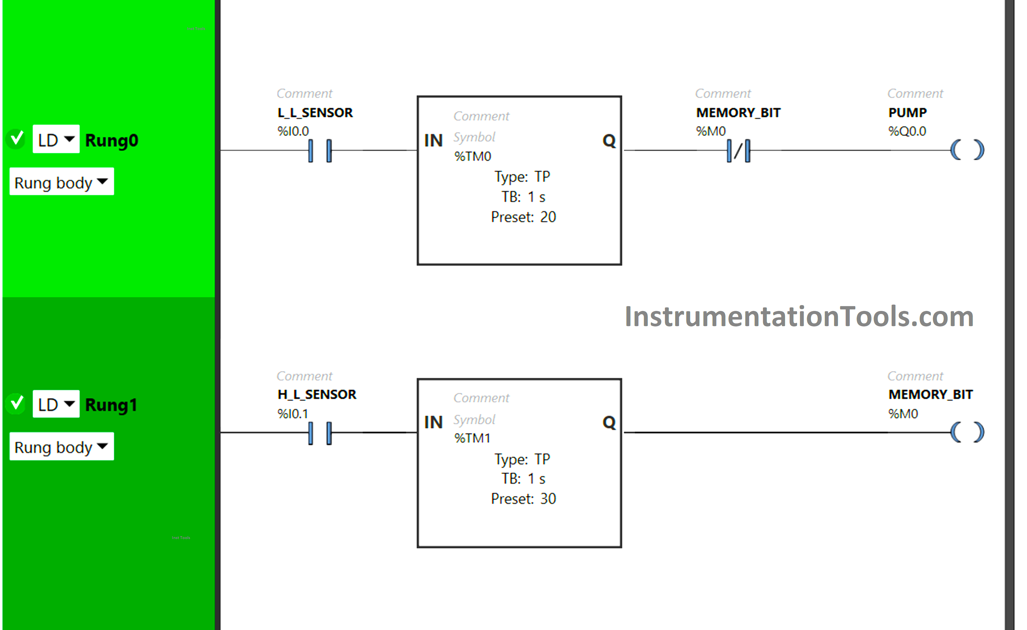
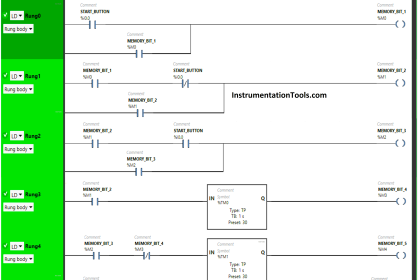
Example PLC Program to Control a Pump based on Level Sensors

Program Description

We have used Normally Open Contacts for low-level sensor as well as high-level sensor.

We have also used the Normally Closed Contact for Memory (M0) bit in Rung0.

For the Pump, Timer Function Block Type TP is used.

To keep the Pump ON for 20 seconds, Timer Function Block type TP (TM0) is used.

Timer Function Block type TP (TM2) is also used for Memory Bit (M0) to keep it ON for 30 seconds.

To keep the Pump OFF for 30 seconds, Memory Bit taken as Normally Closed Contact in Rung0 is used.

Test Case

Now we simulate our PLC program and see the results.

When the Low-level sensor gets activated (detects the tank is low), the Timer functional block type TP (TM0) will allow the signal to flow for a period of 20 seconds only. (as shown in below image)
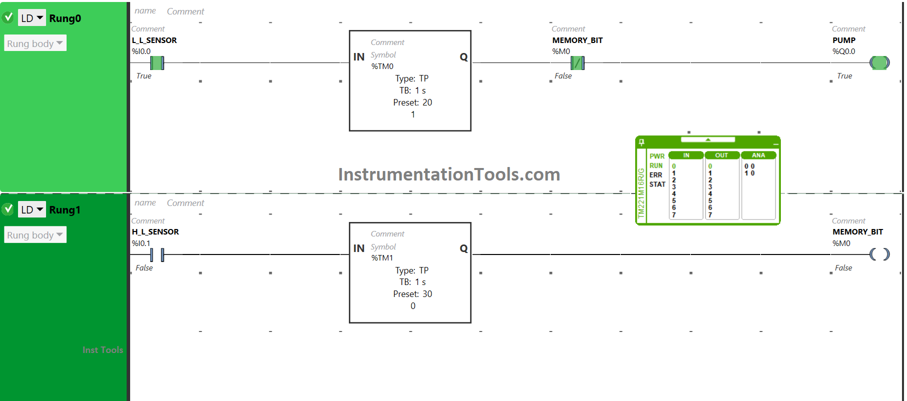
Controlling Water Level in the PLC Ladder Logic Program

The memory bit (M0) will also allow the signal as it is in a false state. As a result, the Pump will be turned ON. After 20 seconds, the signal will not flow because of the Timer functional block type TP (TM0).

The pump will turn OFF after being ON for 20 seconds.

When a high-level sensor gets activated i.e., when the tank is full, Timer functional block TP (TM1) will allow the signal to flow for an interval of  30 seconds. (as shown in below image)
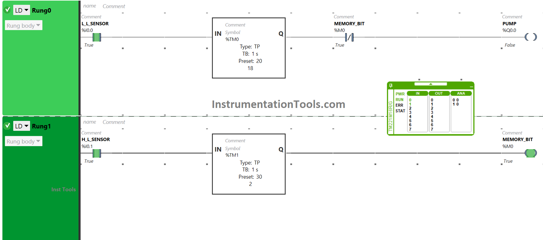
Ladder Logic PLC Programming of a Water Pumping System

As a result, the Memory bit (M0) will become true only for 30 seconds. Then, in Rung0, the memory bit (M0) used as Normally Closed Contact will not allow a signal for 30 seconds. As a result, the output Pump will turn OFF for a period of 30 seconds.

In a nutshell, when the low-level sensor detects that the level of the tank is low, the pump gets turned ON for 20 seconds and when the high-level sensor detects that the level of the tank is high, the pump gets turned OFF for 30 seconds.

If you liked this article, please subscribe to our YouTube Channel for PLC and SCADA video tutorials.

You can also follow us on Facebook and Twitter to receive daily updates.

Read Next:

  • Timers in PLC Programming Tutorials
  • Design Ladder Diagram from Boolean Logic
  • Electrical Ladder Diagram Control with Timers
  • Latching and Unlatching in PLC Programming
  • Electrical Cabinet Air Conditioner Maintenance
Don't Miss Our Updates
Be the first to get exclusive content straight to your email.
We promise not to spam you. You can unsubscribe at any time.
Invalid email address
You've successfully subscribed !
Overview of SIEMENS PLC – S7-1500, S7-1200, S7-400, S7-300
DeMorgan’s Theorems using Ladder Diagram
FactoryTalk Studio and SQL Server for Data Logging
Siemens PLC programming: BCD, Integer, Double Integer, Real
3 Phase Motor Control using PLC Ladder Logic
Share This Article
Facebook Whatsapp Whatsapp LinkedIn Copy Link
Share
Leave a Comment

Leave a Reply Cancel reply

Your email address will not be published. Required fields are marked *

Stay Connected

128.3kFollowersLike
69.1kFollowersFollow
208kSubscribersSubscribe
38kFollowersFollow

Recent Comments

  • MIHARITSOA Aina Sitraka on Top Non-PLC Certification Courses for Automation Professionals
  • Vaishnavi on Free Instrumentation Course for Trainee Engineers
  • anuj kapoor on DCS Program to Maintain Draft in Furnace
  • anuj kapoor on IoT based Smart Boiler Control System with Cloud PLC and SCADA

Related Articles

Connection between PLC and Contactor

Contactor – Basics, Wiring, Connection with PLC

Data Handling Instructions in PLC Programming

Data Handling Instructions in PLC Programming

Principle of Operation of PLC

Principle of Operation of PLC

Example of PLC Programming based on Logic Circuit

Example of PLC Programming based on Logic Circuit

PLC Star-Delta starter with interlock

Schneider PLC Example Program for Star-Delta System

Web SCADA HMI

Web-based SCADA HMI Software

Studio 5000 Programming Three Motors with Fixed Priorities

Studio 5000: Programming Three Motors with Fixed Priorities

PLC Programming for Sequential Batch Mixing System

PLC Programming for Sequential Batch Mixing System

More Articles

Selection of Weighing Balance

Selection of Weighing Balance and Weight for Calibration

Difference between Motion Controller and PLC

Difference between Motion Controller and PLC

GuideLines for Loop Checks

How to Do Loop Checks During Plant Pre-Commissioning

How a Level Switch Works

How to Start Writing SCL in Siemens PLC

Rules for Writing SCL Language in Tia Portal

Symbol of Transistor

Power Transistor – Structure, Biasing, Characteristics, Advantages

Programmable Logic Controller Practice Tests

Programmable Logic Controller Practice Tests

General Specification of Thermowell

General Specification of Thermowell

Follow US
All rights reserved. Reproduction in whole or in part without written permission is prohibited.
Welcome Back!

Sign in to your account

Username or Email Address
Password

Lost your password?