PLC tutorial explaining step by step procedure to program PLC for motor starter.
Motor starters are of many types however the scope of this PLC tutorial is confined to simple motor starter.
It should have the following provisions.
- Push button to start the motor : The motor should continue to rotate even when the push button is released.
- Stop Push button to halt the motor after it started.
- Over current protection : In case of over load, the motor should stop automatically by the signal coming from contactors of overload relay.
- Limit switch : It should prevent the motor from starting and can also stop the running motor.
- The motor starter should also have indicator (Lights) to show ON or OFF status of motor.
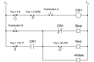
Motor Electrical Schematic :

The above figure shows the physical layout of motor starter however this would be designed through ladder logic in this PLC tutorial.
Above figure does not show limit switch because it depends on external interlock like say level switch, flow switch, pressure switch etc… depending on application. if interlock not required then simply remove the symbol from the diagram and connect with simple wire.
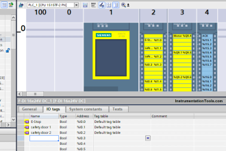
Ladder diagram for Motor starter :
Following figure shows the ladder diagram for motor starter.

Start Button I1 :
Normally open contact (Make contact) is used because the motor should only start when the button is pressed.
Stop Button I2 :
Normally close (break contact) contact is used because the button should normally be closed or high so that the motor keeps on running. It should open when the button is pressed. It is opposite to start push button.
Overload relay I3 :
In normal condition, this relay should allow the motor to rotate so normally close contact is selected for it. In case of overload it will stop the motor by opening its contact.
Limit switch I4 :
The motor should only rotate when the limit switch is closed therefore normally open contact is used.
Output Q1, Q2, Q3 :
Relay coil Q1, Q2 and Q3 represent motor output, motor indication ON and indication OFF respectively.
ON indicator gets input from normally open input which depends upon output Q1. OFF indicator is fed by normally close input which depends upon output Q2.
Input Q1 ( for continuous rotation):
Since it is required that once push button is pressed, motor should run continuously even if the push button is released.
To achieve this part, an input Q1 (normally open) is used and connected in parallel with I1. This input depends upon output Q1.
When output is high, input Q1 is also high. Since input Q1 provides parallel path with I1, so if any of them is to be high, motor will run (if other conditions are also satisfied).
Start button (Normally open), stop button (Normally close), overload relay (Normally close) and limit switch (Normally open) are connected in series. So motor will run if start button is pushed, stop button is not pressed, overload relay is not picked and limit switch is closed.
Note : This post for educational or reference purpose only. For a live circuit, there will be some additions to the above circuit like safety related, as per application, some interlocks etc.
If you liked this article, then please subscribe to our YouTube Channel for PLC and SCADA video tutorials.
You can also follow us on Facebook and Twitter to receive daily updates.
Read Next: