PLC Multiple Outputs Configuration useful for PLC Sequence of Outputs or Sequence Logic, PLC Ladder Rung with Two Outputs, PLC Ladder Rung with two inputs & two outputs.
PLC Ladder Rung with Two Outputs
With ladder diagrams, there can be more than one output connected to a contact.
Figure 1.20 shows a ladder program with two output coils. When the input contacts close, both the coils give outputs.
Also Read: PLC Latching Output Configuration

Example
In Some cases it is required to start two pumps in parallel by pressing a single start button then the above logic may be useful.
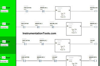
PLC Program with Two Inputs & Two Outputs
For the ladder rung shown in Figure 1.21, output A occurs when input A occurs.
Output B only occurs when both input A and input B occur.

Example:
Say we have a Single Start button to Start two pumps in parallel. But we have extra Start Permissive for Pump B only and it must be started on satisfying the permissive only.
Note that there is no permissive for Pump A in the above example. So Pump A will start on Pressing Start Button and Pump B will start on Satisfying the Start Permissive & with Start button pressing.
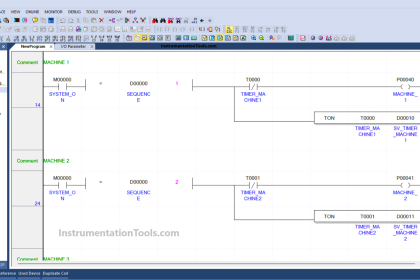
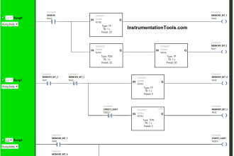
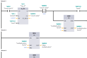
PLC Sequence of Outputs or Sequence Logic
Such an arrangement enables a sequence of outputs to be produced, the sequence being in the sequence with which contacts are closed.
Figure 1.22 illustrates this with the same ladder program in Mitsubishi and Siemens notations. Outputs A, B and C are switched

on as the contacts in the sequence given by the contacts A, B and C are being closed. Until input A is closed, none of the other outputs can be switched on. When input A is closed, output A is switched on.
Then, when input B is closed, output B is switched on. Finally, when input C is closed, output C is switched on.
The above logic will be useful in sequence logic’s. For example for conveyor belt action, Bag house logic, Sequence of on/off valves operation etc.
Also Read: PLC Logic Functions
If you liked this article, then please subscribe to our YouTube Channel for PLC and SCADA video tutorials.
You can also follow us on Facebook and Twitter to receive daily updates.
Read Next:


hii please check the fig.1.22 last image has some problems please check it and if not so please correct me thanks for your efforts