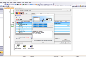
Master PLC mixing logic for liquids using EcoStruxure Machine Expert-Basic Schneider Electric PLC software.
PLC Mixing Logic
This article discusses the Batch Mixing System Sequence which is widely used in industries that produce liquids. When the Batch Mixing system Starts, the Liquid Input Valve will Open and fill the Mixer Tank until it is full.
The Mixer Tank uses sensors (HIGH & LOW) to measure the liquid level in the Tank. When the Mixer Tank is full, the Input Valve will Close and the Mixing Process will continue for 15 seconds.
During the Mixing process, the Input Valve and Output Valve will always be Closed. The Output Valve will automatically Open to release liquid when the Mixing process is complete. Every time the Mixing Process is carried out, the amount will be recorded using the Counter function.
Learn the Operation of the PLC Program
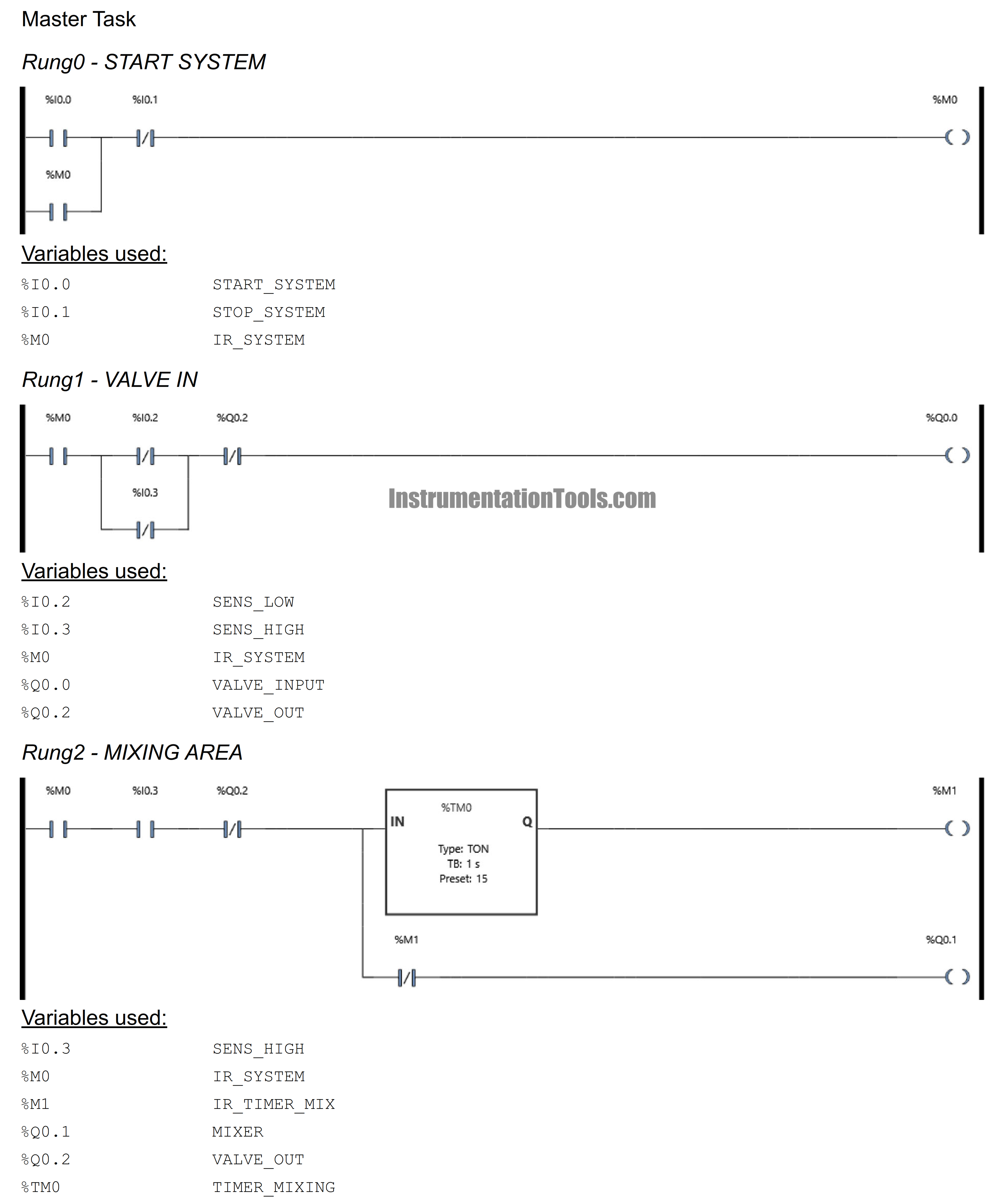
This program uses 3 main buttons, START_SYSTEM (I0.0) functions to Start the system, STOP_SYSTEM (I0.1) functions to Stop the system, and RESET_COUNTER (I0.4) functions to Reset the Counter to zero “0”.
When the Mixer Tank is empty, the NC (Normally Close) contacts of SENS_LOW (I0.2) and SENS_HIGH (I0.3) sensors will turn ON the VALVE_IN (Q0.0). SENS_LOW (I0.2) Functions to detect the low level of liquid in the Mixer Tank and SENS_HIGH (I0.3) to detect the high level of liquid content in the Mixer Tank. VALVE_IN (Q0.0) will be Closed/OFF when SENS_LOW (I0.2) and SENS_HIGH (I0.3) are in the TRUE/HIGH condition.
When VALVE_IN (Q0.0) is Closed, the Mixing process will continue for 15 seconds. The NO (Normally Open) contact of SENS_HIGH (I0.3) which has changed to TRUE/HIGH condition will Activate TIMER_MIXING (TM0). TIMER_MIXING (TM0) will Activate the MIXER Output (Q0.1) for 15 seconds using the NC (Normally Close) contact of the IR_TIMER_MIX (M1) bit memory. After 15 seconds MIXER output (Q0.1) will be Disabled.
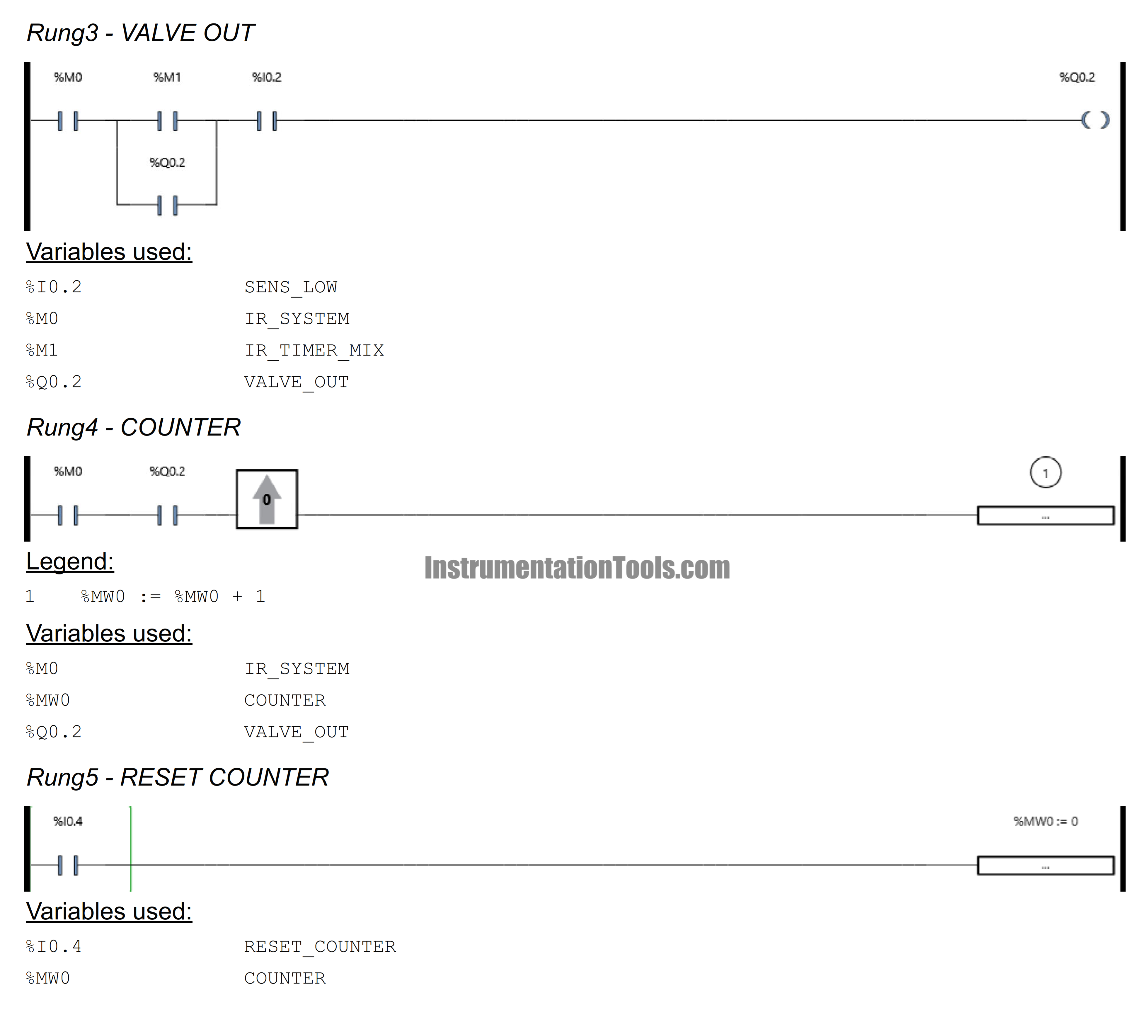
After TIMER_MIXING (TM0) Runs for 15 seconds, the memory bit IR_TIMER_MIX (M1) will be ON for a moment and Activate VALVE_OUT (Q0.2). VALVE_OUT (Q0.2) will remain active even though the memory bit IR_TIMER_MIX (M1) has been Disabled because it uses the Interlock function. VALVE_OUT (Q0.2) will be Disabled when the NO (Normally Open) contact of SENS_LOW (I0.2) changes to LOW/FALSE condition. When VALVE_OUT (Q0.2) is Active, the value on COUNTER (MW0) will increase by (+1).
I/O Details
Addressing Input, Output, TIM, Bit Memory, and Word Memory
| Comment | Input (I) | Output(Q) | Memory Word | Memory Bits | Timer |
| START_SYSTEM | I0.0 | ||||
| STOP_SYSTEM | I0.1 | ||||
| SENS_LOW | I0.2 | ||||
| SENS_HIGH | I0.3 | ||||
| RESET_COUNTER | I0.4 | ||||
| VALVE_IN | Q0.0 | ||||
| MIXER | Q0.1 | ||||
| VALVE_OUT | Q0.2 | ||||
| IR_SYSTEM | M0 | ||||
| IR_TIMER_MIX | M1 | ||||
| COUNTER | MW0 | ||||
| TIMER_MIXING | TM0 |
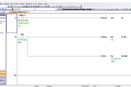
PLC Program
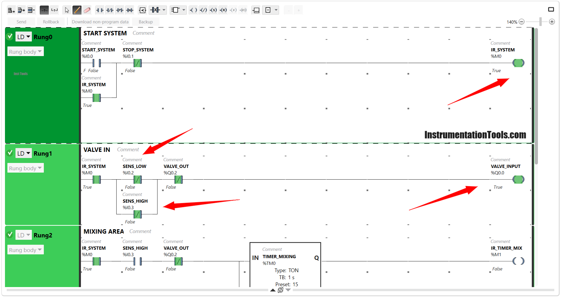
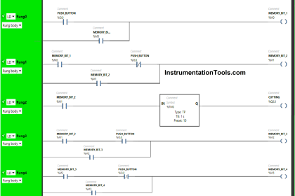
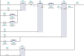
The image above shows the conditions when the system Started. The IR_SYSTEM (M0) bit memory is Active because the START_SYSTEM (I0.0) push button is pressed. The memory bit IR_SYSTEM (M0) remains Active due to the latching. The IR_SYSTEM (M0) bit memory will only be Disabled when STOP_SYSTEM (I0.1) is Enabled.
In Rung-1, you can see that VALVE_INPUT (Q0.0) is Active because the NC (Normally Close) contacts of SENS_LOW (I0.2), SENS_HIGH (I0.3), and VALVE_OUT Q0.2) are still in LOW/FALSE condition.
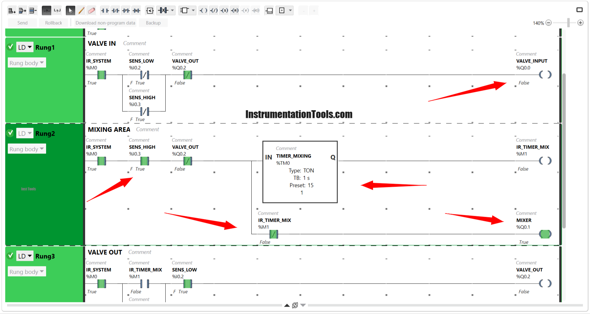
On Rung-2, it can be seen that VALVE_INPUT (Q0.0) is Disabled. TIMER_MIXING (TM0) Starts counting because the NO (Normally Open) contact of SENS_HIGH (I0.3) has become TRUE/HIGH.
Due to the NC (Normally Close) contact of the IR_TIMER_MIX (M1) bit memory, MIXER (Q0.1) becomes Active. MIXER (Q0.1) will Deactivate when the Timer has reached the value of 15 seconds.
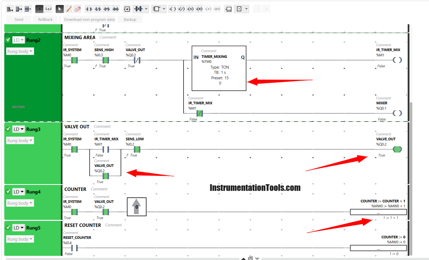
The image above shows the condition when MIXER (Q0.1) is Disabled and VALVE_OUT (Q0.2) is Active. The VALVE_OUT (Q0.2) output will remain active until the NO (Normally Open) contact of SENS_LOW (I0.2) changes to LOW/FALSE.
On Rung-4, it can be seen that COUNTER (MW0) has a value of “1”, meaning that the Mixing process has Run 1 time. Even though VALVE_OUT (Q0.2) is still active, the value of COUNTER (MW0) will only increase (+1) because of the Rising Edge function.
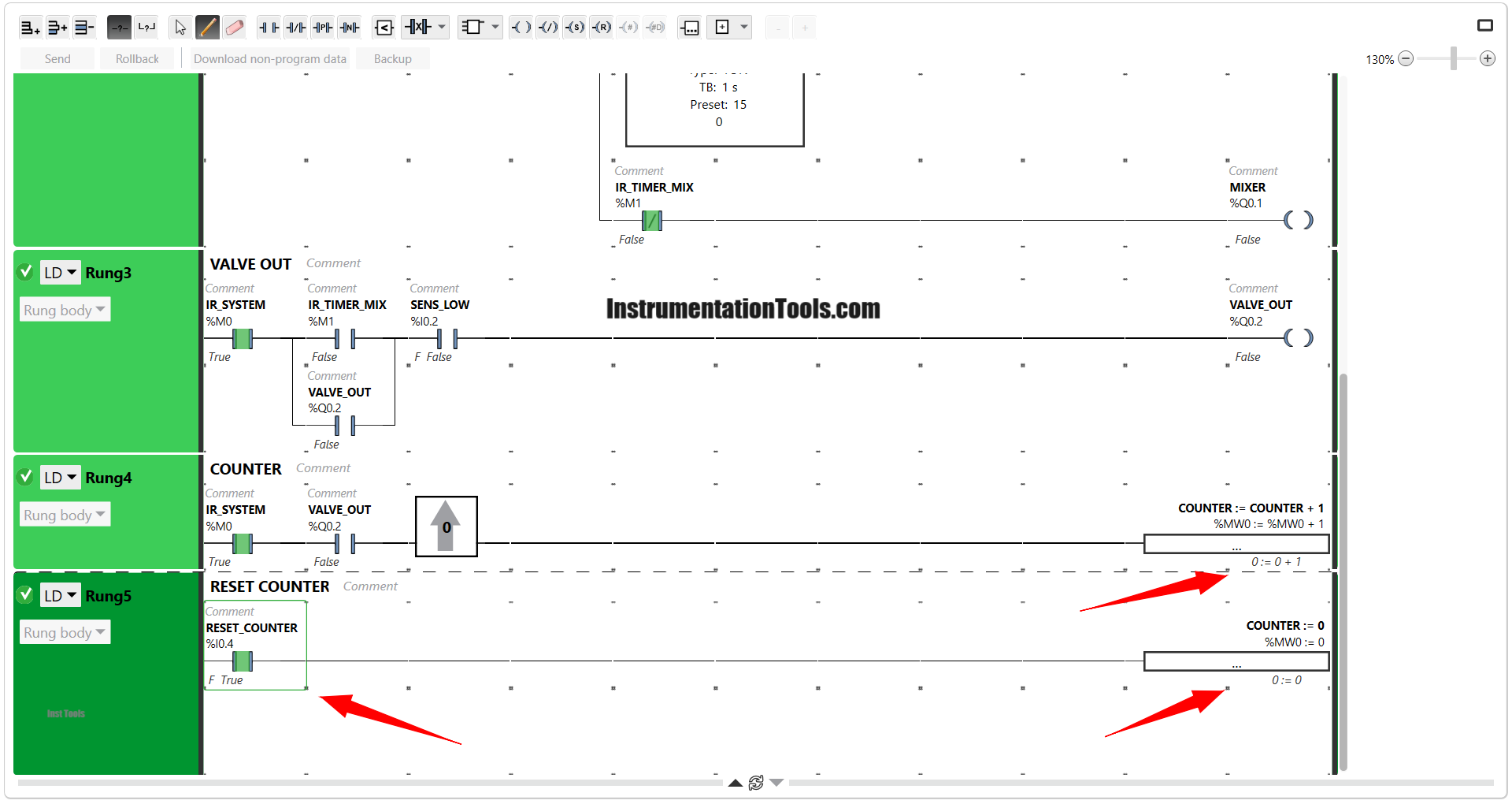
The image above shows the condition when the RESET_COUNTER button (I0.4) is Activated, it can be seen in the Operation Block that the value of COUNTER (MW0) has become zero “0”.
If you liked this article, please subscribe to our YouTube Channel for PLC and SCADA video tutorials.
You can also follow us on Facebook and Twitter to receive daily updates.
Read Next:
- PLC Program for Two-Way Switch Logic
- PLC Scaling Program for Control Valve
- Heating and Mixing of Products using PLC Logic
- Batch Mixing with PLC Ladder Logic Program
- Ecostruxure Machine Expert HVAC Software