There are often situations where it is necessary to hold an output energized, even when the input ceases.
A simple example of such a situation is a motor, which is started by pressing a push button switch. Though the switch contacts do not remain closed, the motor is required to continue running until a stop push button switch is pressed.
The term latch circuit is used for the circuit used to carry out such an operation. It is a self-maintaining circuit in that, after being energized, it maintains that state until another input is received.
PLC Latching Function
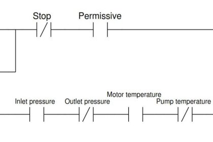
An example of a latch circuit is shown in Figure 1.18. When the input A contacts close, there is an output. However, when there is an output, another set of contacts associated with the output closes.
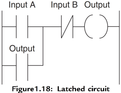
These contacts form an OR logic gate system with the input contacts. Thus, even if the input A opens, the circuit will still maintain the output energized. The only way to release the output is by operating the normally closed contact B.
Also Read: PLC Logic Functions
As an illustration of the application of a latching circuit, consider a motor controlled by stop and start push button switches and for which one signal light must be illuminated when the power is applied to the motor and another when it is not applied.
Figure 1.19 shows the ladder diagram with Mitsubishi notation for the addresses.
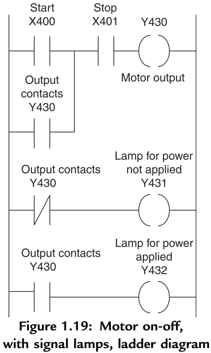
Note that the stop contacts X401 are shown as being programmed as open. If the stop switch used is normally closed then X401 receives a start-up signal to close. This gives a safer operation than programming X401 as normally closed.
X401 is closed when the program is started. When X400 is momentarily closed, Y430 is energized and its contacts close. This results in latching and also the switching off of Y431 and the switching on of Y432.
To switch the motor off, X401 is pressed and opens. Y430 contacts open in the top rung and third rung, but close in the second rung. Thus Y431 comes on and Y432 off.
Latching is widely used with start-ups so that the initial switch on of an application becomes latched on.
Also Read: Introduction to PLC Ladder Diagrams
If you liked this article, then please subscribe to our YouTube Channel for PLC and SCADA video tutorials.
You can also follow us on Facebook and Twitter to receive daily updates.
Read Next:
