In the PLC emergency stop example program, when the emergency button is pressed, the elevator stops immediately and doors open.
Note: This is an example of PLC logic to practice programming with basic applications. This is for students to learn PLC.
Emergency Stop Example Program
Problem Statement:
Design a PLC ladder logic for the following application.
We are using three toggle switches to control the Elevator and Doors.
When the Emergency Button is pressed, stop the elevator immediately. Open the doors once stopped.
When the Reset Button is pressed, it clears the faults, i.e. the doors will close and the Elevator will start again.
PLC Automation Training
Inputs and Outputs
Digital Inputs:
Start Button: I0.0
Emergency Button: I0.1
Reset Button: I0.2
Digital Outputs:
Elevator: Q0.0
Doors: Q0.1
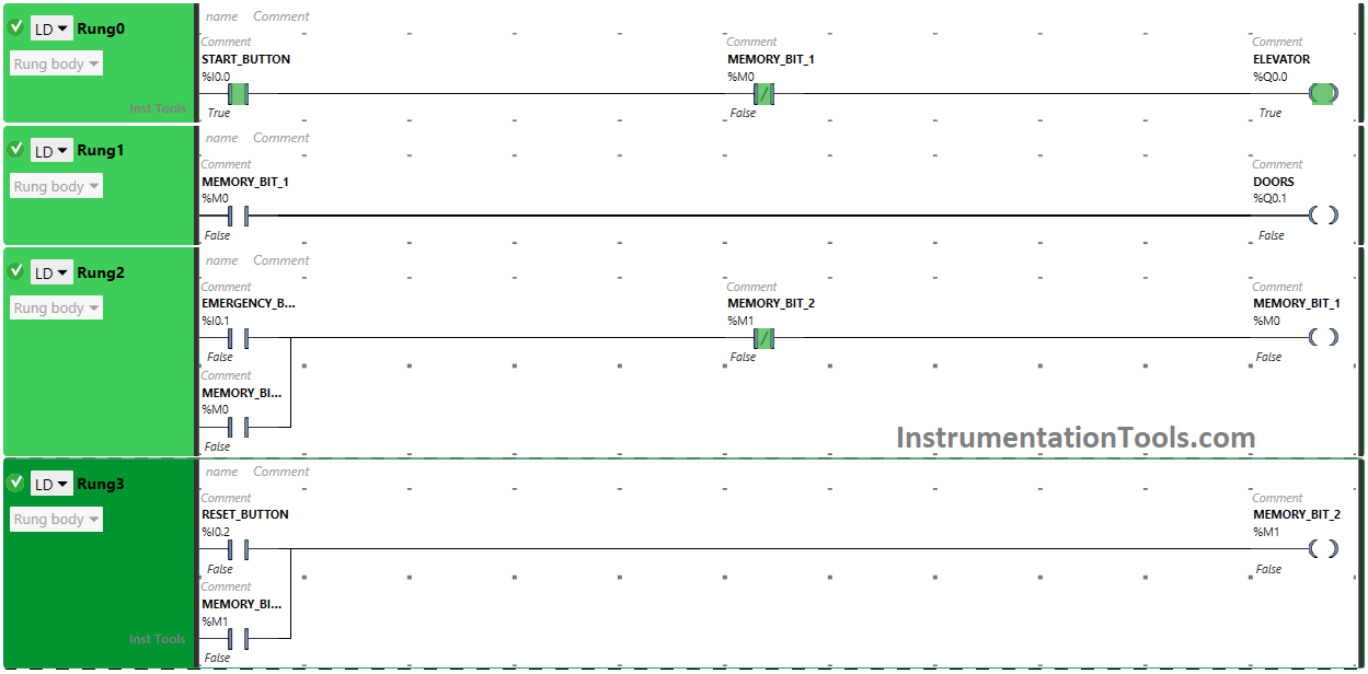
Ladder Logic
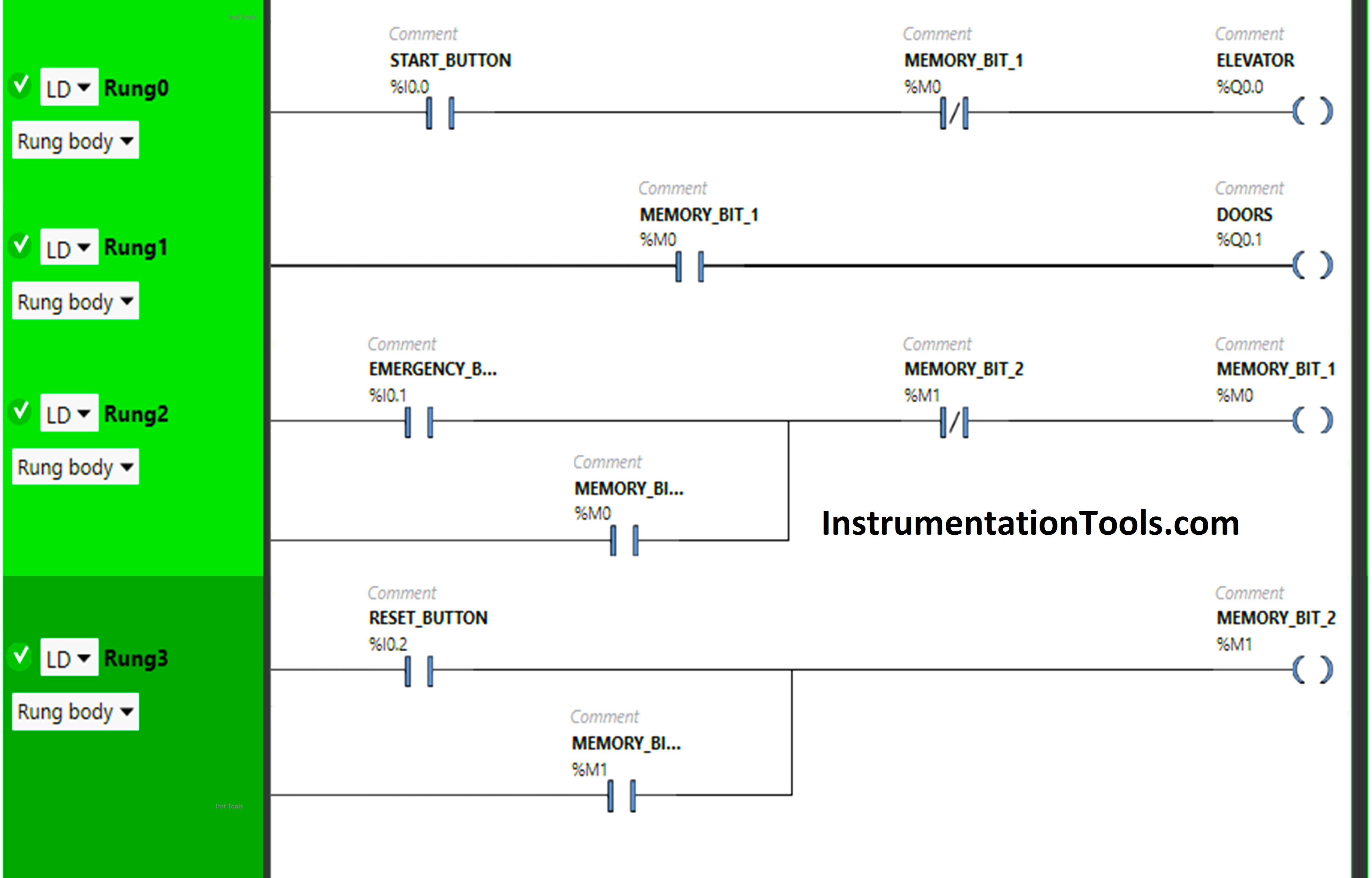
Program Description
We have used Normally Open Contacts for Start Button(I0.0), Emergency Button (I0.1), Reset Button (I0.2), Memory Bit 1 (M0), and Memory Bit 2 (M1).
We have used Normally Closed Contacts for Memory Bit 1 (M0) and Memory Bit 2 (M1).
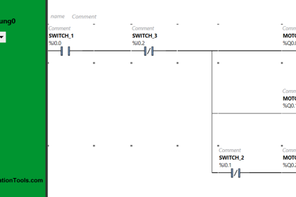
In Rung 0:
- Normally Open Contact is used for the Start Button (I0.0) to Turn ON the output Elevator (Q0.0).
- Normally Closed Contact is used for Memory Bit 1 (M0) to turn OFF the output Elevator (Q0.0).
In Rung 1:
- Normally Open Contact is used for Memory Bit 1 (M0) to Turn ON the output Doors (Q0.1).
In Rung 2:
- Normally Open Contact is used for the Emergency Button (I0.1) to Turn ON Memory Bit 1 (M0).
- Normally Closed Contact is used for Memory Bit 2 (M1) to turn OFF Memory Bit 1 (M0).
- Memory Bit 1 (M0) is latched so that when the Emergency Button (I0.1) is turned OFF, Memory Bit 1 (M0) still remains ON.
In Rung 3:
- Normally Open Contact is used for the Reset Button (Q0.2) to Turn ON Memory Bit 2 (M0).
- Memory Bit 2 (M1) is latched so that when the Reset Button (I0.2) is turned OFF, Memory Bit 2 (M1) still remains ON.
Simulation Results
Now we will simulate our PLC logic and discuss the results.
When the Emergency Button is pressed
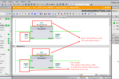
When the Start Button (I0.0) is turned ON, the output Elevator (Q0.0) will turn ON as Normally Open Contact used for the Start Button (I0.0) will be in True state and allow the signal to flow through it.
In a false State, Normally Closed Contact used for Memory Bit 1 (M0) will also pass the signal to the output Elevator (Q0.0) and the output Elevator (Q0.0) will turn ON.
When the Emergency Button (I0.1) is pressed in Rung2, Memory Bit 1 (M0) will turn ON as Normally Open Contact used for Emergency Button (I0.1) will be in True state and allow the signal to flow through it.
In a false State, Normally Closed Contact used for Memory Bit 2 (M1) will also pass signal to Memory Bit 1 (M0), and Memory Bit 1 (M0)will turn ON. Memory Bit 1 (M0) is latched so that when the Emergency Button (I0.1) is turned OFF, Memory Bit 1 (M0) still remains ON.
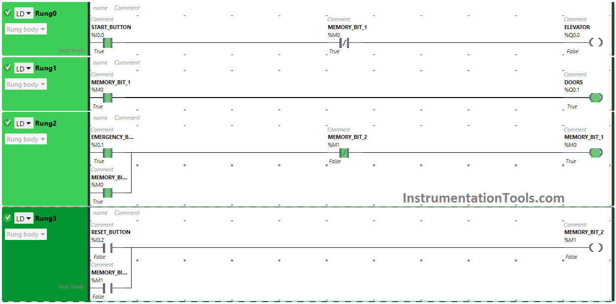
When Memory Bit 1 (M0) turns ON in Rung2, Normally Closed Contact used for Memory Bit 1 (M0) in Rung0 will be in True State and does not allow the signal to flow through it and the output Elevator (Q0.0) will turn OFF (Elevator will Stop immediately).
Also when Memory Bit 1 (M0) turns ON in Rung2, Normally Open Contact used for Memory Bit 1 (M0) will be in True state and will pass the signal to turn ON the output Doors (Q0.1) and the output Doors will turn ON (Doors will Open).
When the Reset Button is pressed
When Reset Button (I0.2) is pressed in Rung3 (the fault is cleared), Memory Bit 2 (M1) will turn ON as in True state, Normally Open Contact used for Reset Button (I0.2) will pass the signal to turn ON Memory Bit 2 (M1). Memory Bit 2 (M1) is latched so that when the Reset Button (I0.2) is turned OFF, Memory Bit 2 (M1) still remains ON.
When Memory Bit 2 (M1) turns ON in Rung3, Normally Closed Contact used for Memory Bit 2 (M1) in Rung2 will be in True State and does not allow the signal to flow through it and Memory Bit 1 (M0) will turn OFF.
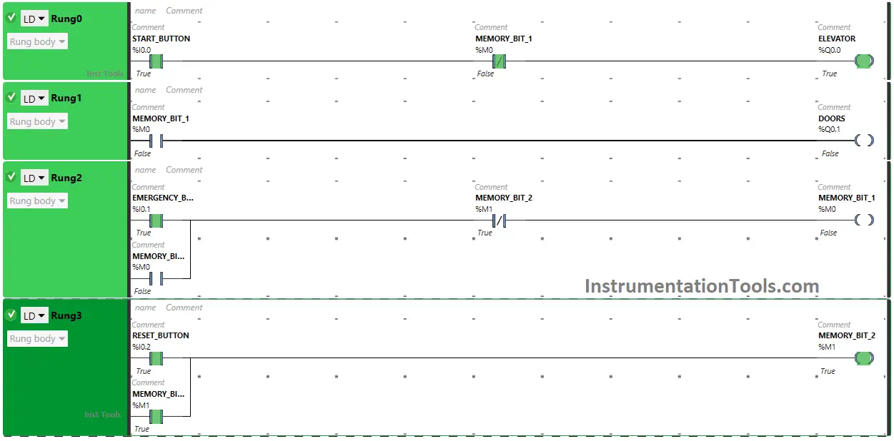
When Memory Bit 1 (M0) turns OFF in Rung2, Normally Open Contact used Memory Bit 1 (M0) will be in a false state and does not allow the signal to flow through it and the output Doors (Q0.1) will turn OFF ( Doors will close).
Also when Memory Bit 1 (M0) turns OFF in Rung2, Normally Closed Contact used for Memory Bit 1 (M0) in Rung0 will be in a false State and will allow the signal to flow through it and the output Elevator (Q0.0) will turn ON (Elevator will start again).
If you liked this article, please subscribe to our YouTube Channel for PLC and SCADA video tutorials.
You can also follow us on Facebook and Twitter to receive daily updates.
Read Next:
- Single Loop Controller Problems
- Shift and Rotate Instructions in PLC
- PLC Logic Auto Sugar Bag Filling Station
- SCADA Level Control System Software
- PLC Programming Two-Hand Control Logic