If timers and counters values are written to the PLC program, they should be validated by the PLC for reasonableness and verify backward counts below zero.
| Security Objective | Target Group |
| The integrity of PLC variables | Integration / Maintenance Service Provider Asset Owner |
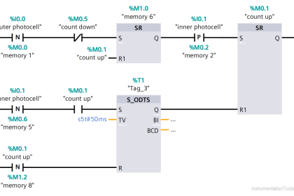
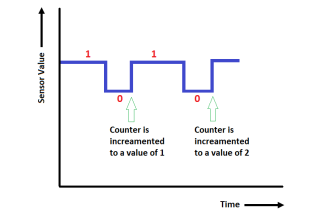
Validate Timers and Counters
Timers and counters can technically be preset to any value. Therefore, the valid range to preset a timer or counter needs should be restricted to meet the operational requirements.
If remote devices such as an HMI write timer or counter values to a program:
- do not let the HMI write to the timer or counter directly but go through a validation logic
- validate presets and timeout values in the PLC
Validation of timer and counter inputs is easy to directly do in the PLC (without the need for any network device capable of Deep Packet Inspection) since the PLC “knows” what the process state or context is. It can validate “what’ it gets and “when” it gets the commands or setpoints.
Example
During PLC startup, timers and counters are usually preset to certain values.
If there is a timer that triggers alarms at 1.3 seconds, but that timer is preset maliciously to 5 minutes, it might not trigger the alarm.
If there is a counter that causes a process to stop when it reaches 10,000 but that is set it to 11,000 from the beginning, the process might not stop.
Why?
| Beneficial for…? | Why? |
| Security | If I/O, timers, or presets are written directly to I/O, not being validated by the PLC, the PLC validation layer is evaded and the HMI (or other network devices) are assigned an unwarranted level of trust. |
| Reliability | The PLC can also validate when an operator accidentally presets bad timer or counter values. |
| Maintenance | Having valid ranges for timers and counters documented and automatically validated may help when updating logic. |
References
| Standard/framework | Mapping |
| MITRE ATT&CK for ICS | Tactic: TA010 – Impair Process Control Technique: T0836 – Modify Parameter |
| ISA 62443-3-3 | SR 3.5: Input Validation |
| ISA 62443-4-2 | CR 3.5: Input Validation |
| ISA 62443-4-1 | SI-2: Secure coding standards SVV-1: Security requirements testing |
Source: PLC Security