Inst ToolsInst ToolsInst Tools
  • Courses
  • Automation
    • PLC
    • Control System
    • Safety System
    • Communication
    • Fire & Gas System
  • Instrumentation
    • Design
    • Pressure
    • Temperature
    • Flow
    • Level
    • Vibration
    • Analyzer
    • Control Valve
    • Switch
    • Calibration
    • Erection & Commissioning
  • Interview
    • Instrumentation
    • Electrical
    • Electronics
    • Practical
  • Q&A
    • Instrumentation
    • Control System
    • Electrical
    • Electronics
    • Analog Electronics
    • Digital Electronics
    • Power Electronics
    • Microprocessor
  • Request
Search
  • Books
  • Software
  • Projects
  • Process
  • Tools
  • Basics
  • Formula
  • Power Plant
  • Root Cause Analysis
  • Electrical Basics
  • Animation
  • Standards
  • 4-20 mA Course
  • Siemens PLC Course
Reading: Pitot Tube Working Principle
Share
Notification Show More
Font ResizerAa
Inst ToolsInst Tools
Font ResizerAa
  • Courses
  • Design
  • PLC
  • Interview
  • Control System
Search
  • Courses
  • Automation
    • PLC
    • Control System
    • Safety System
    • Communication
    • Fire & Gas System
  • Instrumentation
    • Design
    • Pressure
    • Temperature
    • Flow
    • Level
    • Vibration
    • Analyzer
    • Control Valve
    • Switch
    • Calibration
    • Erection & Commissioning
  • Interview
    • Instrumentation
    • Electrical
    • Electronics
    • Practical
  • Q&A
    • Instrumentation
    • Control System
    • Electrical
    • Electronics
    • Analog Electronics
    • Digital Electronics
    • Power Electronics
    • Microprocessor
  • Request
Follow US
All rights reserved. Reproduction in whole or in part without written permission is prohibited.
Inst Tools > Blog > Animation > Pitot Tube Working Principle

Pitot Tube Working Principle

Pitot Tube measures the difference between total pressure and static pressure and it is converted into a proportional flow rate.

Last updated: October 31, 2023 3:07 pm
Editorial Staff
Animation Flow Measurement
2 Comments
Share
6 Min Read
SHARE

The Pitot tube is named after Henri Pitot who used a bent glass tube to measure velocities in a river in France in the 1700s. Pitot tubes can be very simple devices with no moving parts used to measure flow velocities.

Contents
Pitot TubeAveraging Pitot tubeAdvantages of the Pitot tubeDisadvantages of the Pitot tubeApplications for the Pitot tube

Pitot tubes are a common type of insertion flowmeter. The below animation shows the basics for a Pitot tube, where pressure is generated in a tube facing the flow, by the velocity of the fluid.

This ‘velocity’ pressure is compared against the reference pressure (or static pressure) in the pipe, and the velocity can be determined by applying a simple equation.

Pitot Tube
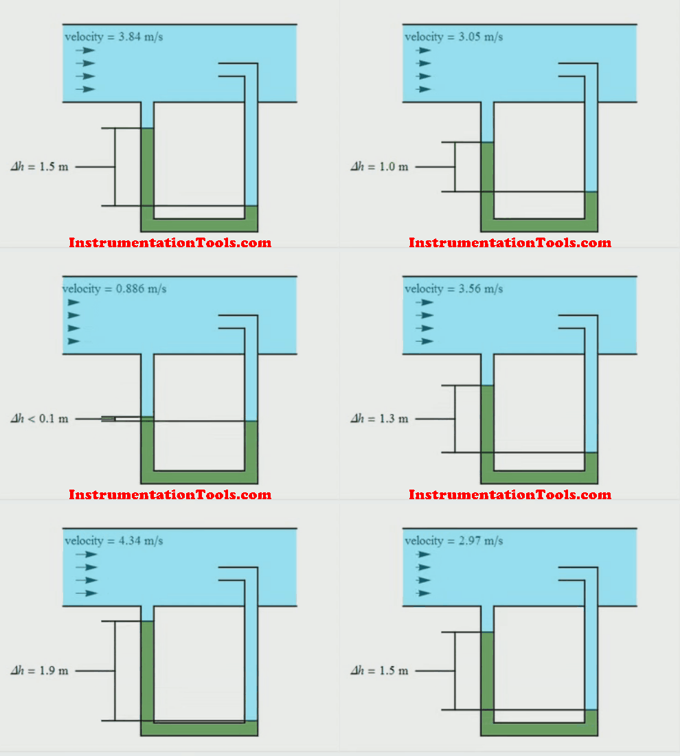
Pitot Tube Working Principle Animation

Note: In Animation from right to left: The tube inserted in the center of the pipe is used to measure Total Pressure and the next second tube is used to measure the static pressure.

When the flow rate through the pipe changes, the pressures at the total pressure tube and static pressure tube vary with respect to the flow velocities. The difference between the total pressure and static pressure is used to measure the proportional flow rate passing through the pipe.

A DP-type transmitter is used to measure the difference between total pressure and static pressure and it is converted into a proportional flow rate.
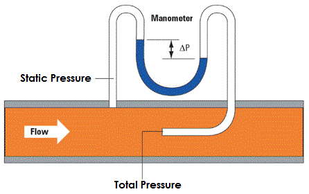
Pitot Tube Flow Meter

In practice, two tubes inserted into a pipe would be cumbersome, and a simple Pitot tube will consist of one unit as shown in the Below Figure. Here, the hole measuring the velocity pressure and the holes measuring the reference or static pressure are incorporated into the same device.

Pitot Tube Installation

Because the simple Pitot tube (Above Figure ) only samples a single point, and, because the flow profile of the fluid (and hence velocity profile) varies across the pipe, accurate placement of the nozzle is critical. To avoid this type of problem we are using averaging pitot tubes.

Note that a square root relationship exists between velocity and pressure drop (see Below Equation). This limits the accuracy to a small turndown range.

Pitot Tube Calculation Formula

Where:

u1 =The fluid velocity in the pipe
Δp =Dynamic pressure – Static pressure
ρ =Density

There are some practical limitations to the use of a pitot-static tube:

  1. If the velocity is low, the difference in pressures is very small and hard to accurately measure with the transducer. Errors in the instrument could be greater than the measurement! So pitot-static tubes don’t work very well for very low velocities.
  2. If the velocity is very high (supersonic), we’ve violated the assumptions of Bernoulli’s equation and the measurement is wrong again. At the front of the tube, a shock wave appears that will change the total pressure. There are corrections for the shock wave that can be applied to allow us to use pitot-static tubes for high-speed aircraft.
  3. If the tubes become clogged or pinched, the resulting pressures at the transducer are not the total and static pressures of the external flow. The transducer output is then used to calculate a velocity that is not the actual velocity of the flow.

Averaging Pitot tube

The averaging Pitot tube (Below Figure) was developed with a number of upstream sensing tubes to overcome the problems associated with correctly siting the simple type of Pitot tube.

These sensing tubes sense various velocity pressures across the pipe, which are then averaged within the tube assembly to give a representative flow rate of the whole cross-section.
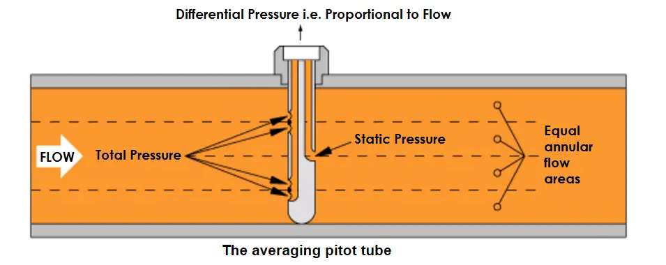
Averaging Pitot Tube Working Principle

Advantages of the Pitot tube

  • Presents little resistance to flow.
  • Inexpensive to buy.
  • Simple types can be used on different-diameter pipes.

Disadvantages of the Pitot tube

  • Turndown is limited to approximately 4:1 by the square root relationship between pressure and velocity.
  • If steam is wet, the bottom holes can become effectively blocked. To counter this, some models can be installed horizontally.
  • Sensitive to changes in turbulence and needs careful installation and maintenance.
  • The low pressure drop measured by the unit, increases uncertainty, especially on steam.
  • Placement inside the pipework is critical.

Applications for the Pitot tube

  • Occasional use to provide an indication of flow rate
  • Determining the range over which a more appropriate steam flow meter may be used.

Reference: spiraxsarco

If you liked this article, then please subscribe to our YouTube Channel for Instrumentation, Electrical, PLC, and SCADA video tutorials.

You can also follow us on Facebook and Twitter to receive daily updates.

Read Next:

  • Coriolis Meter Construction
  • Optical flow meter Principle
  • Doppler Ultrasonic Meter
  • Turbine Flow Meter Theory
  • What is a Thermal Mass Meter
Don't Miss Our Updates
Be the first to get exclusive content straight to your email.
We promise not to spam you. You can unsubscribe at any time.
Invalid email address
You've successfully subscribed !

Continue Reading

What is an Orifice Flange? – Purpose and Applications
Solenoid Valve Working Animation
How does SMPS Works? – Switched Mode Power Supply
TOC Analyzer Working Principle
Types of Flow Meters
Troubleshooting Magnetic Flow Meters Common Problems
Share This Article
Facebook Whatsapp Whatsapp LinkedIn Copy Link
Share
2 Comments
  • AYON BHOWMIK says:
    June 3, 2016 at 5:01 pm

    Thank you sir for the article , it really helped a lot to clear the concept.

    Reply
  • GOURI SHANKAR PATTNAIK says:
    November 10, 2016 at 6:59 pm

    Thanks sir

    Reply

Leave a Reply Cancel reply

Your email address will not be published. Required fields are marked *

Stay Connected

128.3kFollowersLike
69.1kFollowersFollow
210kSubscribersSubscribe
38kFollowersFollow

Categories

Explore More

Fire Water Sprinklers Working Principle
Troubleshooting Ultrasonic Flow Meter Common Problems
Coriolis Flowmeter Advantages and Limitations
Piston Flow Meters Working Principle with Animation
Differential Pressure (DP) Flow Meters Range Calculation Methods
Float Level Switch Working Principle Animation
Beam Detectors Working Principle Animation
Impeller Flow Sensor Working Principle and Animation

Keep Learning

Applications of Tilting Level Switch

How Tilt Level Switch Works ?

Heat Tracing Problems

Heat Tracing Problems

Displacer Level Sensor Working Animation

Displacer Level Sensor Working Animation

Configure the Instruments in Flow Control Loop

Configure the Instruments in Flow Control Loop

Turbine Flow Meter Calibration

How to do Turbine Flow Meter Verification?

Flow Meter Reading Unstable

What Factors Affect the Stability of Flow Meter Readings?

Hot wire Anemometer Principle

Hot Wire Anemometer Principle and Types

Open Channel Flow Measurement Animation

Open Channel Flow Measurement Principle

Learn More

Basics of FOUNDATION Fieldbus

Difference between Fieldbus, Profibus and HART Protocols

What Every Instrument Engineer Should Know

Common Mistakes in Instrumentation

PLC Motor Control Ladder Logic

PLC Program for Star Delta Motor Starter

PLC Program for Two ways switch logic for staircase light

PLC Program for Two Way Switch Logic

Transmission and Distribution Objective Questions and Answers

175+ Transmission and Distribution Objective Questions and Answers

Modern Cement Kiln Drive

Cement kilns, Rotary Drum Driers Simplest Electrical Drive

Control Valve Whisper Trim Cage

Problem with Choked Control Valve with Whisper Trim Cage

Button 3C of the Matrix Keypad is pressed

How the Matrix Keypad works with a Micro controller?

Menu

  • About
  • Privacy Policy
  • Copyright

Quick Links

  • Learn PLC
  • Helping Hand
  • Part Time Job

YouTube Subscribe

Follow US
All rights reserved. Reproduction in whole or in part without written permission is prohibited.
Welcome Back!

Sign in to your account

Username or Email Address
Password

Lost your password?