PID controller simulator represents a very useful tool to understand as algorithm PID works.
In addition, the concept as direct or indirect controller action, 4-20 mA analog input/output signal, fail close or fail open control valve are fundamental to determine the correct implementation of the closed-loop control.
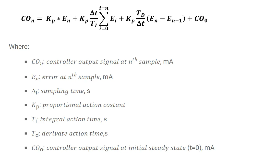
This worksheet simulates a simple level of control in a tank. The algorithm PID, for discrete values, is used to simulate the process:

For those interested, I would like to share the excel document in which it is possible to see the calculations.
It was considered that the controller has in the input (Cin) and in output (CO) the variables according to the standard 4-20 mA.
Sampling time ∆t is equal to 1 s. The system is initially in a steady-state with a settable input flow rate equal to the output flowrate.
At t = 0 it takes a step disturbance on the discharge line by means of the pump.
Through mass balance, the actual level (Present Value) is calculated. Obviously, in real-case, there is a Level Transmitter that “read” and communicate at the controller the PV.
It is possible to put in the system a dead time just to see the effect on the PID controller.
The algorithm PID determines the control action on the control valve that modify the inlet flowrate.
The control valve has a linear characteristic: Fin= % opening valve / 100 * Fmax, in.
To disable the derivative action is sufficient to set Td = 0 (refer to sheet “Calculation”, cell J8) while to disable the integral action set value 0 in the cell J9, excel sheet “Calculation”.
Note: this excel file simulates an “academic” version of the PID controller.
Author: Domenico Luca Romilio
If you liked this article, then please subscribe to our YouTube Channel for PLC and SCADA video tutorials.
You can also follow us on Facebook and Twitter to receive daily updates.
Learn an example PLC program to control a pump based on level sensors using ladder…
In the PLC timer application for security camera recording, when motion is detected then camera…
In this example, we will learn batch mixing with PLC ladder logic program using timer…
This PLC example on manufacturing line assembly is an intermediate-level PLC program prepared for the…
In this article, you will learn the PLC programming example with pushbutton and motor control…
This article teaches how to convert Boolean logic to PLC programming ladder logic with the…
View Comments
Thx for article it is very helpful to me
great
thank you