Inst ToolsInst ToolsInst Tools
  • Courses
  • Automation
    • PLC
    • Control System
    • Safety System
    • Communication
    • Fire & Gas System
  • Instrumentation
    • Design
    • Pressure
    • Temperature
    • Flow
    • Level
    • Vibration
    • Analyzer
    • Control Valve
    • Switch
    • Calibration
    • Erection & Commissioning
  • Interview
    • Instrumentation
    • Electrical
    • Electronics
    • Practical
  • Q&A
    • Instrumentation
    • Control System
    • Electrical
    • Electronics
    • Analog Electronics
    • Digital Electronics
    • Power Electronics
    • Microprocessor
  • Request
Search
  • Books
  • Software
  • Projects
  • Process
  • Tools
  • Basics
  • Formula
  • Power Plant
  • Root Cause Analysis
  • Electrical Basics
  • Animation
  • Standards
  • 4-20 mA Course
  • Siemens PLC Course
Reading: PID Simulator Download
Share
Font ResizerAa
Inst ToolsInst Tools
Font ResizerAa
  • Courses
  • Design
  • PLC
  • Interview
  • Control System
Search
  • Courses
  • Automation
    • PLC
    • Control System
    • Safety System
    • Communication
    • Fire & Gas System
  • Instrumentation
    • Design
    • Pressure
    • Temperature
    • Flow
    • Level
    • Vibration
    • Analyzer
    • Control Valve
    • Switch
    • Calibration
    • Erection & Commissioning
  • Interview
    • Instrumentation
    • Electrical
    • Electronics
    • Practical
  • Q&A
    • Instrumentation
    • Control System
    • Electrical
    • Electronics
    • Analog Electronics
    • Digital Electronics
    • Power Electronics
    • Microprocessor
  • Request
Follow US
All rights reserved. Reproduction in whole or in part without written permission is prohibited.
Inst Tools > Blog > PLC Tutorials > PID Simulator Download

PID Simulator Download

The PID controller simulator represents a very useful tool to understand the basic PID algorithm. Download and run the simulations.

Last updated: March 4, 2021 10:48 am
Editorial Staff
PLC Tutorials Control Systems Excel Tools
3 Comments
Share
2 Min Read
SHARE

PID controller simulator represents a very useful tool to understand as algorithm PID works.

Contents
PID AlgorithmClosed-Loop ControlDownload PID Simulator

In addition, the concept as direct or indirect controller action, 4-20 mA analog input/output signal, fail close or fail open control valve are fundamental to determine the correct implementation of the closed-loop control.

PID Algorithm

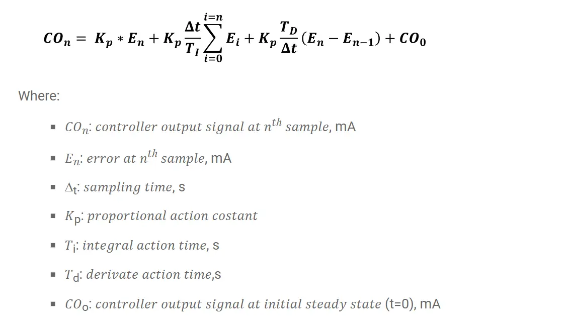
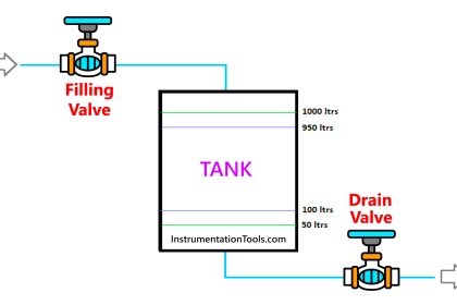
This worksheet simulates a simple level of control in a tank. The algorithm PID, for discrete values, is used to simulate the process:

PID algorithm

For those interested, I would like to share the excel document in which it is possible to see the calculations.

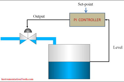
It was considered that the controller has in the input (Cin) and in output (CO) the variables according to the standard 4-20 mA.

Closed-Loop Control

Closed Loop

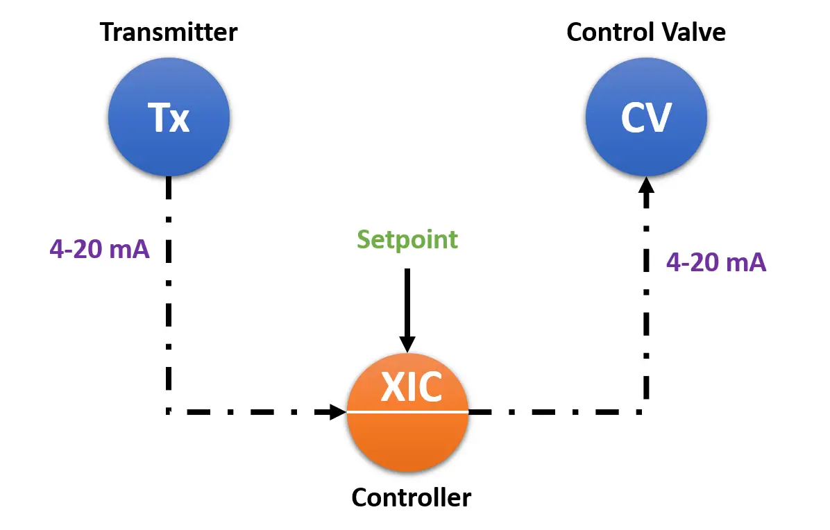
Sampling time ∆t is equal to 1 s. The system is initially in a steady-state with a settable input flow rate equal to the output flowrate.

At t = 0 it takes a step disturbance on the discharge line by means of the pump.

Through mass balance, the actual level (Present Value) is calculated. Obviously, in real-case, there is a Level Transmitter that “read” and communicate at the controller the PV.

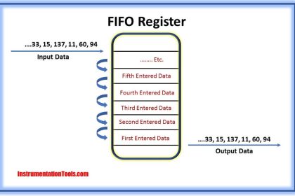
It is possible to put in the system a dead time just to see the effect on the PID controller.

The algorithm PID determines the control action on the control valve that modify the inlet flowrate.

The control valve has a linear characteristic: Fin= % opening valve / 100 * Fmax, in.

To disable the derivative action is sufficient to set Td = 0 (refer to sheet “Calculation”, cell J8) while to disable the integral action set value 0 in the cell J9, excel sheet “Calculation”.

PID Simulator Download

Note: this excel file simulates an “academic” version of the PID controller.

Download PID Simulator

Author: Domenico Luca Romilio

If you liked this article, then please subscribe to our YouTube Channel for PLC and SCADA video tutorials.

You can also follow us on Facebook and Twitter to receive daily updates.

Don't Miss Our Updates
Be the first to get exclusive content straight to your email.
We promise not to spam you. You can unsubscribe at any time.
Invalid email address
You've successfully subscribed !

Continue Reading

Ziegler-Nichols Open-Loop Method
Managed Switch vs Unmanaged Switch
What is Fail-safe in Siemens PLC?
PLC Temperature Control using Pulse Width Modulation (PWM)
Step-by-Step Guide to Choose Right Fuse for a Panel
Automated Garage Gate Control – PLC Ladder Logic
Share This Article
Facebook Whatsapp Whatsapp LinkedIn Copy Link
Share
3 Comments
  • Jumel Navidad says:
    January 25, 2023 at 3:16 am

    Thx for article it is very helpful to me

    Reply
  • Raed says:
    August 23, 2023 at 3:01 pm

    great

    Reply
  • Zhao Haiyang says:
    November 23, 2023 at 3:12 pm

    thank you

    Reply

Leave a Reply Cancel reply

Your email address will not be published. Required fields are marked *

Stay Connected

128.3kFollowersLike
69.1kFollowersFollow
210kSubscribersSubscribe
38kFollowersFollow

Categories

Explore More

PLC Instruction List for Motor Reverse and Forward Direction
Programmable Logic Controller Practice Tests
Foundation Fieldbus – Advantages, Limitations, Architecture
What is a GSD File and Why it is required?
Siemens Tia Portal PLC Training Course
PLC Pump Control: 10 seconds ON & 20 seconds OFF
Establish Communication Between Two PLC Via PROFIBUS Protocol
Introducing PLC Programming using LogixPro Simulator Software

Keep Learning

Industrial Automation and Control

100+ Questions and Answers on Industrial Automation and Control

Gas Turbine Temperature Control using Siemens Tia Portal

Gas Turbine Temperature Alarms using Siemens TIA Portal

Basic Process Control System

Basic Process Control System

4-20mA Current Loop for Flow Transmitter and Control Valve Positioner

4–20 mA Process Control Loops

Ziegler-Nichols closed-loop Tuning

Ziegler-Nichols Closed-Loop Method (Ultimate Gain)

Create PLC Program based on Logic Circuit

Create PLC Program based on Logic Circuit

Types of Interrupts Organization Blocks in Tia Portal

Types of Interrupt OB in Siemens Tia Portal

Design Process Control & Safety Systems

Design View of Supplying Process Control and Safety Systems

Learn More

Instrumentation Engineering Root Cause Analysis

Instrumentation Engineering Problems Solved – Root Cause Analysis

Three-Phase Power Supply

Single Phase versus Three Phase Power

Claw Machine PLC Programming

Doll Claw Machine using Omron PLC Programming

control valve parts

Common Terms Used in Control Valves

HART Layers vs OSI Layers

HART Communication Tutorial Part 3

Readings Mismatch between Field & Control Room

Readings Mismatch between Field & Control Room ? Why

How to Select the Right Encoder for Your Machine

How to Select the Right Encoder for Your Machine?

Calculate Total Hydrostatic Pressure at Bottom of Vessel

Calculate Total Hydrostatic Pressure at Bottom of Vessel

Menu

  • About
  • Privacy Policy
  • Copyright

Quick Links

  • Learn PLC
  • Helping Hand
  • Part Time Job

YouTube Subscribe

Follow US
All rights reserved. Reproduction in whole or in part without written permission is prohibited.
Welcome Back!

Sign in to your account

Username or Email Address
Password

Lost your password?