Inst ToolsInst ToolsInst Tools
  • Courses
  • Automation
    • PLC
    • Control System
    • Safety System
    • Communication
    • Fire & Gas System
  • Instrumentation
    • Design
    • Pressure
    • Temperature
    • Flow
    • Level
    • Vibration
    • Analyzer
    • Control Valve
    • Switch
    • Calibration
    • Erection & Commissioning
  • Interview
    • Instrumentation
    • Electrical
    • Electronics
    • Practical
  • Q&A
    • Instrumentation
    • Control System
    • Electrical
    • Electronics
    • Analog Electronics
    • Digital Electronics
    • Power Electronics
    • Microprocessor
  • Request
Search
  • Books
  • Software
  • Projects
  • Process
  • Tools
  • Basics
  • Formula
  • Power Plant
  • Root Cause Analysis
  • Electrical Basics
  • Animation
  • Standards
  • 4-20 mA Course
  • Siemens PLC Course
Reading: P&ID Guidelines for Separator Vessels
Share
Font ResizerAa
Inst ToolsInst Tools
Font ResizerAa
  • Courses
  • Design
  • PLC
  • Interview
  • Control System
Search
  • Courses
  • Automation
    • PLC
    • Control System
    • Safety System
    • Communication
    • Fire & Gas System
  • Instrumentation
    • Design
    • Pressure
    • Temperature
    • Flow
    • Level
    • Vibration
    • Analyzer
    • Control Valve
    • Switch
    • Calibration
    • Erection & Commissioning
  • Interview
    • Instrumentation
    • Electrical
    • Electronics
    • Practical
  • Q&A
    • Instrumentation
    • Control System
    • Electrical
    • Electronics
    • Analog Electronics
    • Digital Electronics
    • Power Electronics
    • Microprocessor
  • Request
Follow US
All rights reserved. Reproduction in whole or in part without written permission is prohibited.
Inst Tools > Blog > Erection & Commissioning > P&ID Guidelines for Separator Vessels

P&ID Guidelines for Separator Vessels

Last updated: September 29, 2016 3:04 pm
Editorial Staff
Erection & Commissioning
No Comments
Share
4 Min Read
SHARE

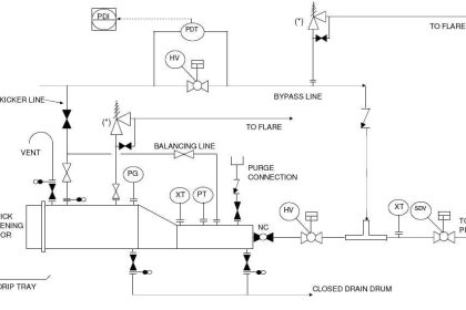
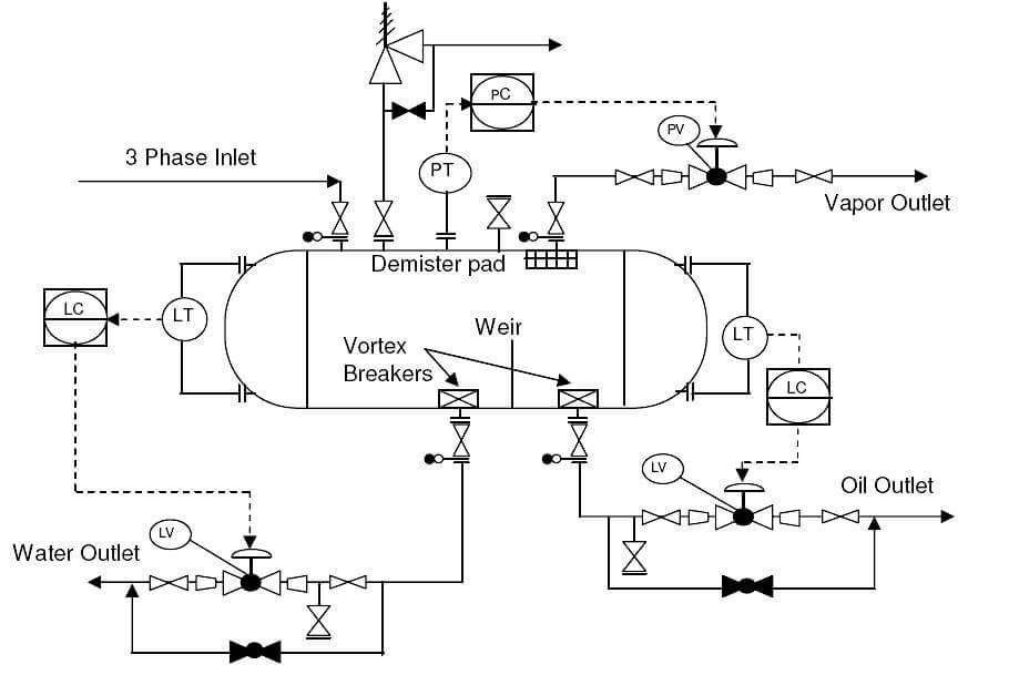
3 phase separators are commonly used in upstream oil and gas industry to separate oil, gas and water stream coming from the oil wells. This typical P&ID arrangement can be modified and used for other separator vessels as well.

Piping and Instrumentation Diagram

  1. Proper vessel symbol should be selected first of all, as shown in the presented drawing. This should be selected from the list of equipment symbols on the legend sheets of a particular project.
  2. Separator vessel internals should then be indicated as per proper symbols on the legend sheets. These internals can be inlet vane, vortex breaker on the outlet lines, demister pads on gas outlets, weir plate separating the oil and water compartments etc.
  3. All the nozzles on the separator vessel should then be correctly represented with size and flanges. This includes inlet and outlet nozzles, drains, vents, PSV connection and instrument nozzles, as shown in the sample drawing presented here. Typical instrumentation on the vessel would be level gauges and transmitters on oil and water compartments of the vessel plus pressure gauge and transmitters linked to pressure control or alarms as applicable.
  4. Inlet and outlet lines are the next to be drawn up. Line number, material class, size etc. is to be correctly assigned to each of the lines.
  5. Isolation valves, spectacle blinds, spacers etc. to be used for maintenance should be drawn up next on the inlet / outlet lines. The spectacle blinds, spacers etc. are usually connected right next to the isolation valves and equipment nozzles, as indicated in the sample drawing presented here.
  6. Instrumentation on the vessel  should be drawn up next. Typically this would include level gauges, level transmitters, pressure gauges, pressure transmitters as per requirement for control, alarm and trip if applicable. The sample drawing presented here only indicates transmitters, but generally they are accompanied by gauges for local indication and also transmitters for alarms and trips.
  7. Various control valves should be drawn up next wherever applicable. Sample drawing indicates level control on oil and water outlet lines. Plus pressure control is indicated on the vapor outlet to flare. These control valves should be equipped with either a bypass or handwheel as per project standards, to continue vessel operation in case of control valve maintenance.
  8. Drains should be provided either on the vessel or on the bottom outlet lines for complete draining of  the vessel and associated piping for maintenance purpose. Sample drawing has indicated drains on the outlet lines through which the vessel and piping can be completely drained. Usually the vessel also has nozzles connecting it directly to the draining system.
  9. Vents can be present either on the vessel itself or on the vapor outlet line, so that the vessel and associated piping can be completely vented for maintenance. Vent connected directly to vessel is indicated in the sample drawing.
  10. In most cases the vessel is provided with a blanketing gas connection. This blanketing connection can be with or without pressure control. Although not indicated in the sample drawing, it is important to consider the blanketing gas connection to the vessel.
  11. For purging the vessel with nitrogen, a connection can be provided directly on the vessel. In some cases purging can be done with steam.
  12. All the guidelines given here are very general and may be modified as per specific requirements of any particular project.
Don't Miss Our Updates
Be the first to get exclusive content straight to your email.
We promise not to spam you. You can unsubscribe at any time.
Invalid email address
You've successfully subscribed !

Continue Reading

Field Instruments Mounting brackets
Impulse Tubing Leak Test Checks
Thermocouple Temperature Measurement Errors
Important Factors Consider during Piping Design
How Not to Install an Instrument and Wrong Practices
Magnetic Flow Meters Installation Guidelines
Share This Article
Facebook Whatsapp Whatsapp LinkedIn Copy Link
Share
Leave a Comment

Leave a Reply Cancel reply

Your email address will not be published. Required fields are marked *

Stay Connected

128.3kFollowersLike
69.1kFollowersFollow
210kSubscribersSubscribe
38kFollowersFollow

Categories

Explore More

P&ID Guidelines for Storage Tanks
P&ID Guidelines for Control Valves
Material Certificate versus Positive Material Identification (PMI)
Pressure Transmitter Heated Enclosures
Wrong Installation of Horn Type Radar Level Transmitter on Sloping Tank
Installation and Calibration of Level Transmitter
Gas Detectors Installation Techniques
P&ID Guidelines for Pig Receivers

Keep Learning

cross

Tube Fitting Types

What is FAT and SAT?

What is FAT and SAT? Difference between them

Turbine Flow Meter Installation Procedure

Piping and Instrumentation Diagram

What is Piping and Instrumentation Diagram (P&ID) ?

magnetic-flow-meter-earthing

Importance of Magnetic Flow Meters Grounding

P&ID Guidelines for Pumps Heat Exchangers

P&ID Guidelines for Pumps Heat Exchangers

Instrumentation Cables Questions Answers

Instrumentation Cables Questions & Answers

5-valve manifold

Pressure Transmitter Vent fittings

Learn More

Ccomparator in PLC Programming

Comparator in PLC Programming

Reduce Control Valve Noise

How to Reduce the Control Valve Noise?

Full Wave Rectifier

Full Wave Rectifier

Claw Machine PLC Programming

Doll Claw Machine using Omron PLC Programming

Tube Fittings - 4

Tube and tube fittings

NO NC Contact Animation

Equivalent Logic Gates using PLC Ladder Diagrams

Electrical Feeder Automation in Smart Grid

Electrical Feeder Automation in Smart Grid

PLC Raw Count Calculation formula for Pressure Transmitter

PLC Raw Count Calculation for Pressure Transmitter

Menu

  • About
  • Privacy Policy
  • Copyright

Quick Links

  • Learn PLC
  • Helping Hand
  • Part Time Job

YouTube Subscribe

Follow US
All rights reserved. Reproduction in whole or in part without written permission is prohibited.
Welcome Back!

Sign in to your account

Username or Email Address
Password

Lost your password?