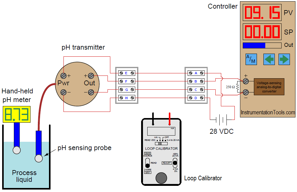
A newly-installed pH transmitter does not seem to be measuring the pH of the process liquid accurately. The indicating controller’s display does not match the display of the hand-held pH meter used by an operator.

The calibrated range of the 4-wire pH transmitter is supposed to be 2 to 12 pH, with a 4 to 20 mA signal output range. An instrument technician begins to diagnose the problem by taking a loop calibrator and measuring the current signal being sent to the indicating controller. The loop calibrator registers 15.43 milliamps.
Based on this information, determine where the problem is in this system. Also, show how the loop calibrator could be connected to the wiring to measure the loop current (specifying the proper calibrator mode as well).
15.43 milliamps of current equates to a percentage value of 71.44%
(15.43 − 4) / 16 × 100% = 71.44%
This, in turn, represents a pH value of:
0.7144 × (12 − 2) + 2 = 9.144 pH
This largely agrees with the controller’s display, which tells us there is a slight calibration error on either the part of the controller or the resistor. The huge discrepancy between this calculated pH value and what the hand-held pH meter registers, however, tells us there is either a problem with the pH transmitter, the pH probe, or the hand-held meter. We may further conclude there is no problem with the 250 resistor or the indicating controller.
The proper setup of the loop calibrator is to place it into the “READ” (measure) mode so that it functions as a simple ammeter, then connect it in series with the output of the 4-wire transmitter. This may be done either with the indicating controller still in the circuit, or removed from the circuit.
Share Your Answer through comments.
Credits: Tony R. Kuphaldt
Lube oil consoles of rotary equipment packages in industrial process plants are usually equipped with…
Rotating equipment packages such as pumps, compressors, turbines need the lube oil consoles for their…
This article explains how to blink lights in ladder logic with a detailed explanation video…
In this article, a simple example will teach you the conversion from Boolean algebra to…
In this article, you will learn the PLC cooking timer example for kitchen automation using…
Learn an example PLC program to control a pump based on level sensors using ladder…
View Comments
Dear All,
The first thing I would do is check the Lab meter with two pH buffer solutions - say 7 & 12 pH.
Clean the process pH probe and check it with the same buffer and note the differences.
The third is to check if the controller output range is set accordingly to the valves PH 2 = 4 mA and pH 12 = 20mA.
If it's good then we can recalibrate the pH probe accordingly.
Rgds SR
Dear All,
I would check a sample to the laboratory then compare the pH value with Portable pH Meter & Transmitter.
After that calibrate pH sensor (Portable pH Meter & Transmitter) with the same buffer, if necessary.
Galih