Instrumentation, Electrical, PLC, Tutorials
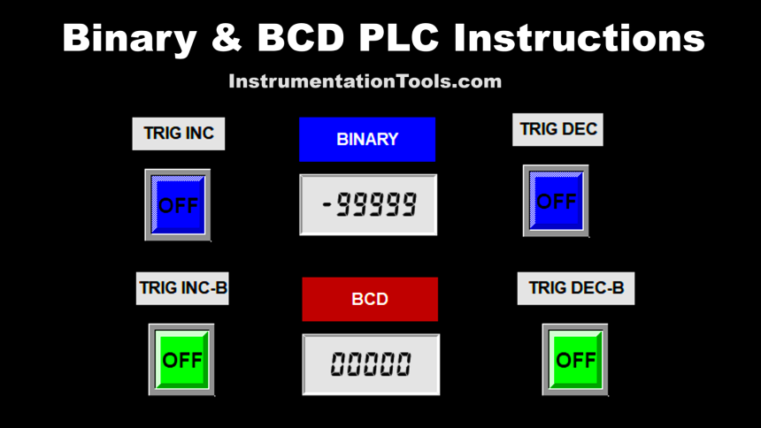
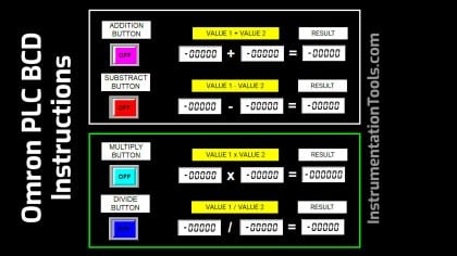
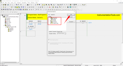
Learn how to use Binary (++/--) and BCD (++B/--B) increment and decrement instructions in Omron PLC using CX-Programmer.
Sign in to your account
Remember me