This article discusses the implementation of a PLC (Programmable Logic Controller) program to control a moving conveyor system integrated with an oven using Siemens TIA-Portal software. In this system, the oven functions to bake products transported by the conveyor. The baking process is carried out in three sequential stages with predetermined durations, followed by a cooling process as the products exit the baking area. The system is also equipped with an automatic counting feature to track the number of products that have completed the baking process.
Program Objective
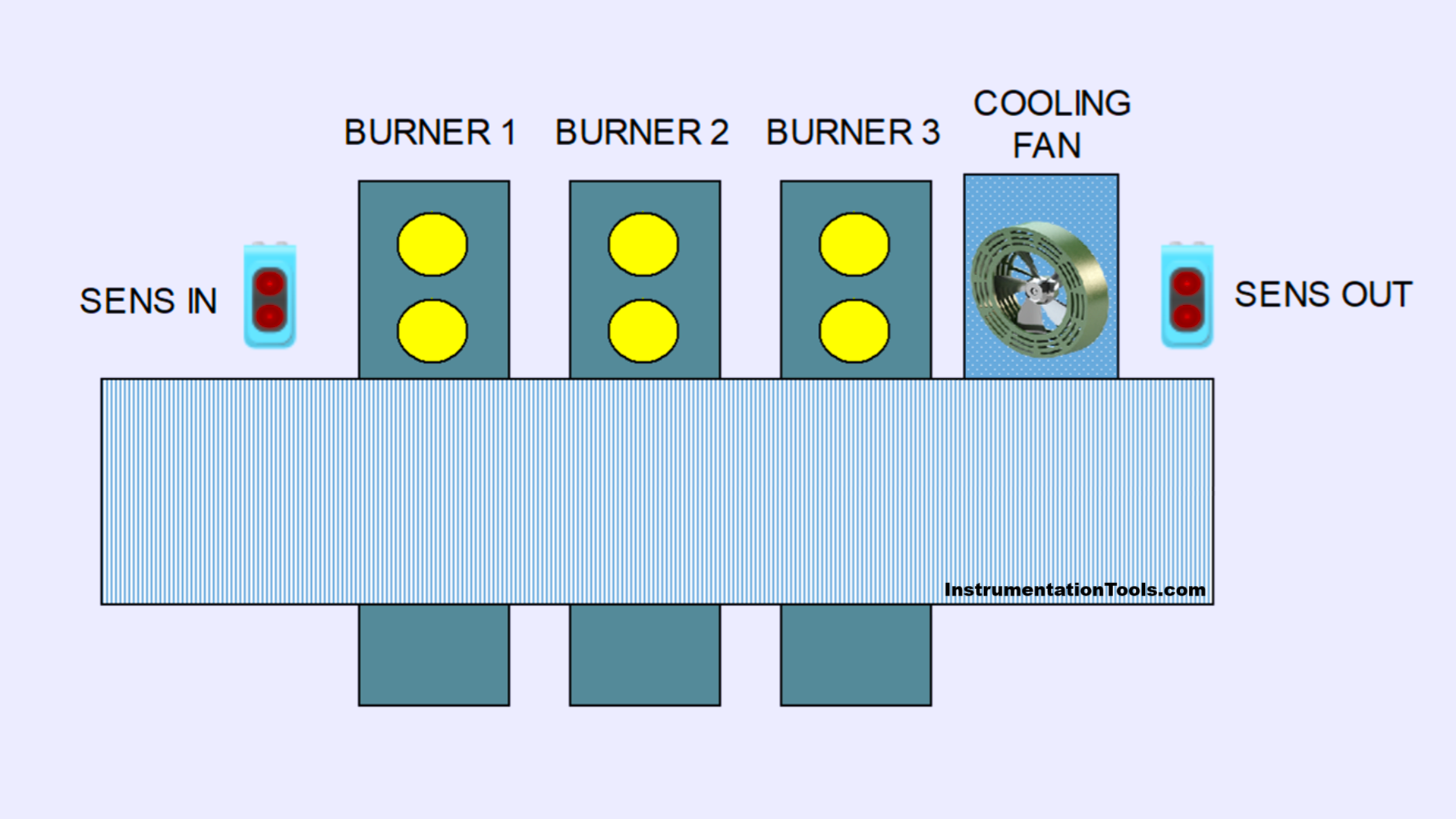
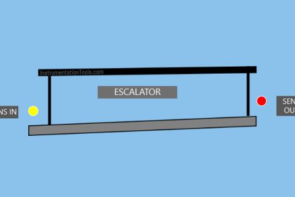
Step-by-Step System:
Standby Mode: The system is in standby condition, ready to start the process.
Conveyor Activation: The conveyor is activated and starts running to transport the product.
Product Detection and Roasting Process:
When the system detects a product on the conveyor, the baking process begins.
a. Burner-1 turns on for 5 seconds.
b. Burner-2 turns on for 6 seconds.
c. Burner-3 turns on for 7 seconds.
Product Cooling: After the baking process is complete, the cooling fan is activated for 4 seconds to lower the product’s temperature.
Product Counting and Return to Standby:
- The system will count the number of products that have completed the entire process.
- After counting is complete, the system returns to standby mode.
Counter Reset: The product count data can be reset using the reset function.
IO Mapping of Siemens TIA Portal
| S.No. | Comment | Input (I) | Output (Q) | Memory Bits | Word Memory | Timers |
|---|---|---|---|---|---|---|
| 1 | START | I0.0 | ||||
| 2 | STOP | I0.1 | ||||
| 3 | SENS_IN | I0.2 | ||||
| 4 | SENS_OUT | I0.3 | ||||
| 5 | RESET_COUNTER | I0.4 | ||||
| 6 | CONVEYOR | Q0.0 | ||||
| 7 | BURNER_1 | Q0.1 | ||||
| 8 | BURNER_2 | Q0.2 | ||||
| 9 | BURNER_3 | Q0.3 | ||||
| 10 | COOLING_FAN | Q0.4 | ||||
| 11 | SYSTEM_ON | M2.0 | ||||
| 12 | IR_TIMER_1 | M2.1 | ||||
| 13 | IR_TIMER_2 | M2.2 | ||||
| 14 | IR_TIMER_3 | M2.3 | ||||
| 15 | IR_TIMER_4 | M2.4 | ||||
| 16 | TEMP1 | M2.5 | ||||
| 17 | TEMP2 | M2.6 | ||||
| 18 | TEMP3 | M2.7 | ||||
| 19 | TEMP4 | M3.0 | ||||
| 20 | COUNTER | MW0 | ||||
| 21 | TIMER_1 | DB1 | ||||
| 22 | TIMER_2 | DB2 | ||||
| 23 | TIMER_3 | DB3 | ||||
| 24 | TIMER_4 | DB4 |
Oven Control with Moving Conveyor
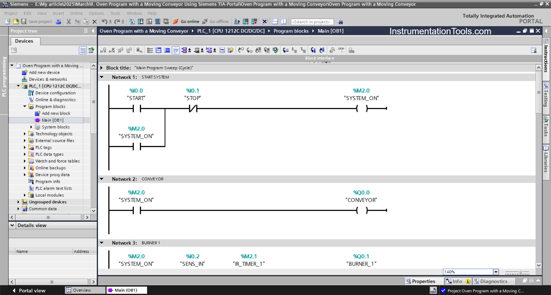
NETWORK 1 (START SYSTEM)
In this Network, the memory bit SYSTEM_ON (M2.0) will be in a HIGH state when the START (I0.0) button is pressed. Even though the START (I0.0) button has been released, the memory bit SYSTEM_ON (M2.0) remains in a HIGH state. Because it uses Latching.
The memory bit SYSTEM_ON (M2.0) will be in a LOW state if the STOP(I0.1) button is pressed.
NETWORK 2 (CONVEYOR)
In this Network, the CONVEYOR (Q0.0) output will turn ON when the NO contact of the memory bit SYSTEM_ON (M2.0) is in a HIGH state.
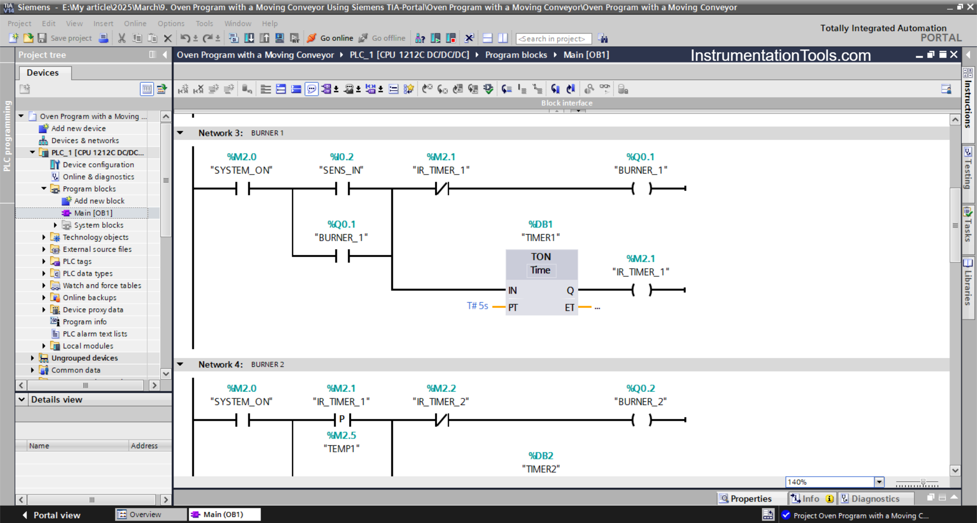
NETWORK 3 (BURNER 1)
The BURNER_1 (Q0.1) output will be ON when the NO contact of the memory bit SYSTEM_ON (M2.0) and the SENS_IN (I0.2) sensor are in the HIGH state. Because it uses Latching, even though the SENS_IN(I0.2) sensor is in the LOW state, the BURNER_1 (Q0.1) output will remain ON.
Next, the TIMER_1 (DB1) timer will start counting up to 5 seconds, and when the timer has finished counting, the memory bit IR_TIMER_1 (M2.1) will be in the HIGH state and the BURNER_1 (Q0.1) output will turn OFF due to the interlock from the memory bit IR_TIMER_1(M2.1).
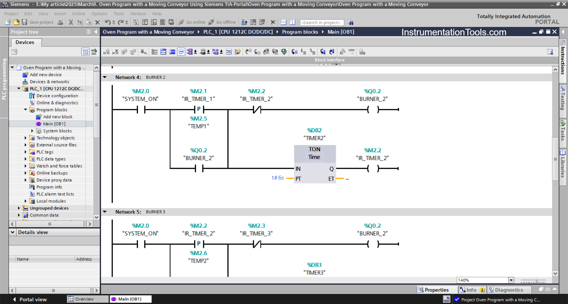
NETWORK 4 (BURNER 2)
The BURNER_2 (Q0.2) output will be ON when the NO contact of the memory bits SYSTEM_ON (M2.0) and IR_TIMER_1 (M2.1) are in the HIGH state. Because it uses Latching, even though the NO contact of the memory bit IR_TIMER_1(M2.1) is in the LOW state, the BURNER_2 (Q0.2) output will remain ON.
Next, the TIMER_2 (DB2) timer will start counting up to 6 seconds, and when the timer has finished counting, the memory bit IR_TIMER_2 (M2.2) will be in the HIGH state and the BURNER_2 (Q0.2) output will turn OFF due to the interlock from the memory bit IR_TIMER_2 (M2.2).
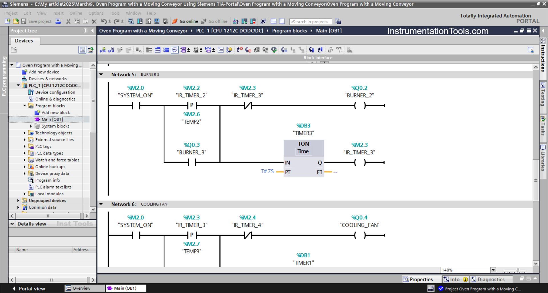
NETWORK 5 (BURNER 3)
The BURNER_3 (Q0.3) output will be ON when the NO contact of the memory bits SYSTEM_ON (M2.0) and IR_TIMER_2 (M2.2) are in the HIGH state. Because it uses Latching, even though the NO contact of the memory bit IR_TIMER_2 (M2.2) is in the LOW state, the BURNER_3 (Q0.3) output will remain ON.
Next, the TIMER_3 (DB3) timer will start counting up to 7 seconds, and when the timer has finished counting, the memory bit IR_TIMER_3 (M2.3) will be in the HIGH state and the BURNER_3 (Q0.3) output will turn OFF due to the interlock from the memory bit IR_TIMER_3 (M2.3).
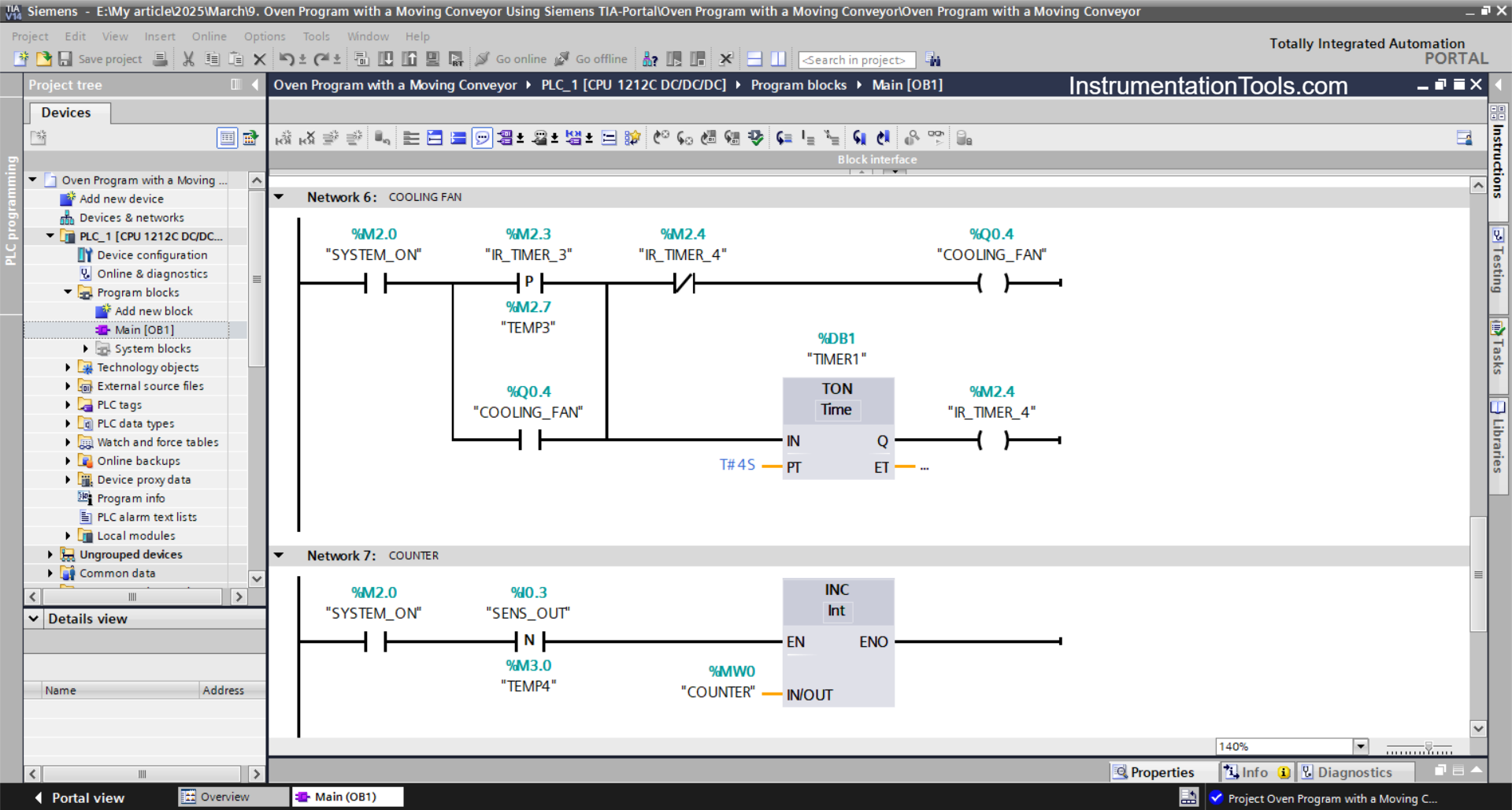
NETWORK 6 (COOLING FAN)
The COOLING_FAN (Q0.4) output will be ON when the NO contact of the memory bits SYSTEM_ON (M2.0) and IR_TIMER_3 (M2.3) are in the HIGH state.
Even though the NO contact of the memory bit IR_TIMER_3 (M2.3) is in the LOW state, the COOLING_FAN (Q0.4) output will remain ON. Because it uses Latching.
Next, the TIMER_4 (DB4) timer will start counting up to 4 seconds, and when the timer has finished counting, the memory bit IR_TIMER_4 (M2.4) will be in the HIGH state and the COOLING_FAN (Q0.4) output will turn OFF due to the interlock from the memory bit IR_TIMER_4 (M2.4).
NETWORK 7 (COUNTER PRODUCT)
In this Network, because it uses the INC Instruction, the value in the memory word COUNTER (MW0) will increase (+1) when the NO contact of the memory bit SYSTEM_ON (M2.0) and the SENS_OUT (I0.3) sensor are in the HIGH state.
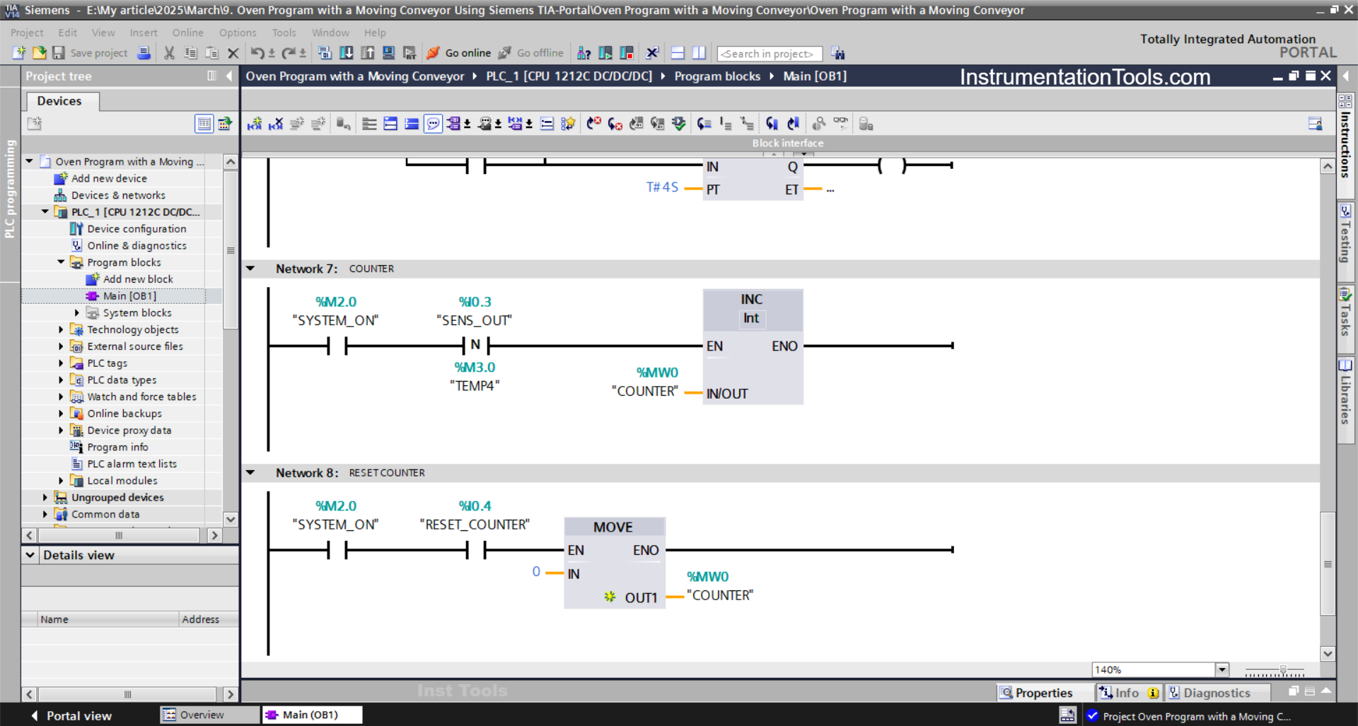
NETWORK 8 (RESET COUNTER)
The value in the memory word COUNTER (MW0) will be reset to zero (0) when the NO contact of memory bit SYSTEM_ON (M2.0) is in a HIGH state and the RESET_COUNTER button (I0.3) has been pressed.
The MOV instruction transfers the value zero to the memory word COUNTER (MW0).
Read Next:
- One Input to Turn ON Multiple Outputs in PLC
- Clock Memory Bits in TIA Portal for Siemens PLC
- Firmware Version of a Siemens PLC Hardware
- PLC Programmer Salary and Future Career Scope
- How to Use an SQL Server with Indusoft Web Studio?