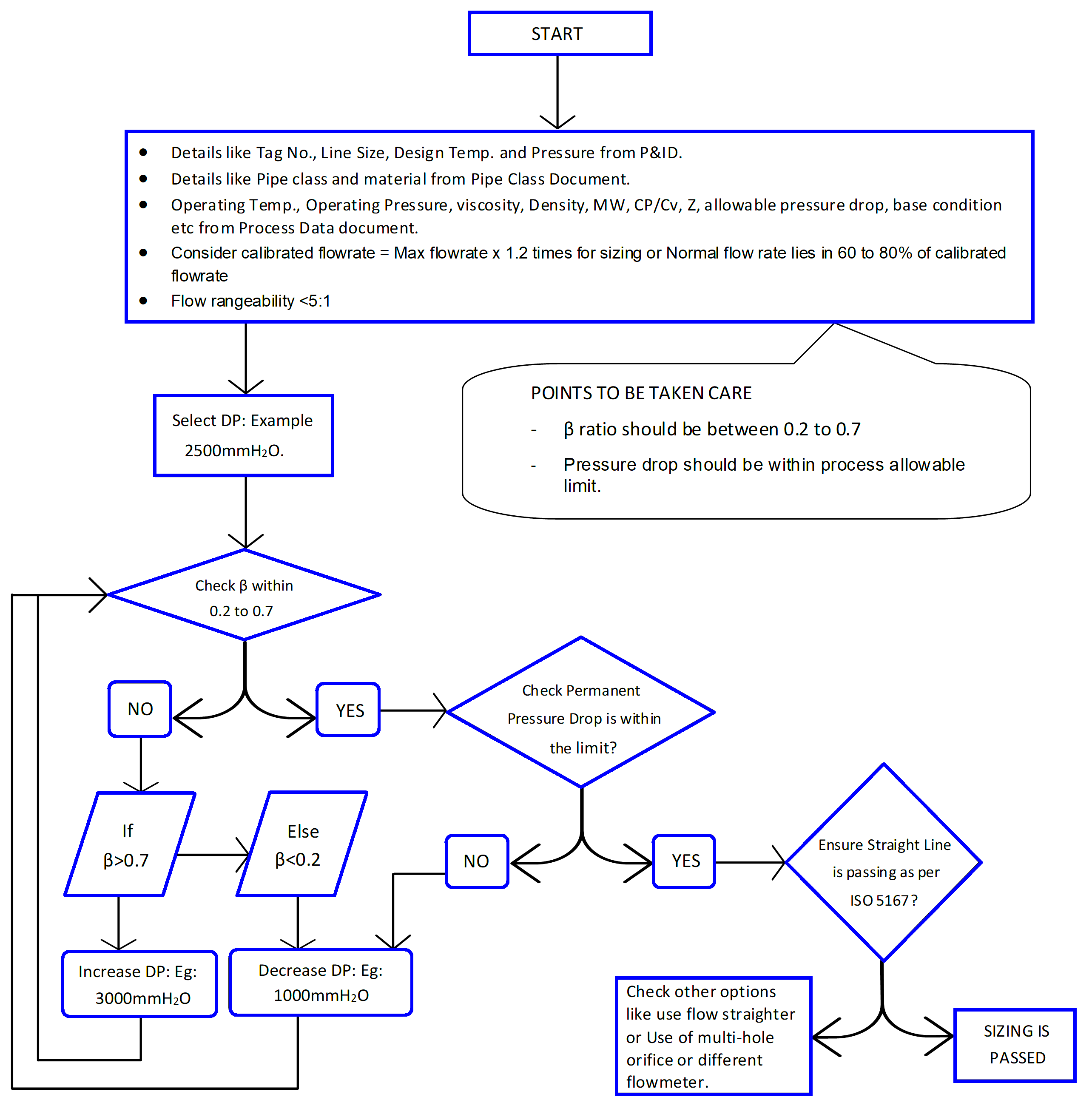
Here we shared the brief details of orifice sizing guidelines and a simple flowchart with basic thumb rules during the design and selection.
Orifice Sizing Guidelines
Follow the below-mentioned summary about orifice selection and sizing.
Check Sizing Standard: ISO 5167; AGA Report No-3; MFC-14M
Orifice Flange standard: ASME B 16.36.
For 2″ lines and above: Orifice plates with flanges can be used.
Integral Orifice: For line sizes equal to / less than 1.5″
D-D/2 tapping to be used for size >14″, Flanged tapping <=14” line size
Flow rangeability: 1:4 ( for closed loops) and 1:5 (for open loops) for orifice
Example – Max flow condition is 45000 Nm/hr; Min flow condition is 10000 Nm3/hr
Then rangeability is 45000/10000 = 4.5 So the orifice can be used for rangeability 5 and below.
Where flow rangeability is between 5:1 to 10:1, Dual Differential pressure transmitters are preferred for better accuracy.
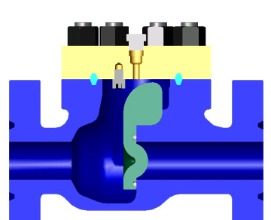
The orifice plate square-edge concentric by default choice.
Quadrant edge for services with low Reynolds e.g. <10000
Conical entrance orifice for services with low Reynolds e.g. <2000
Eccentric / Segmental type of orifice plates shall be used for specific applications
Eccentric type – where fluids carry the gases and Gases carry the liquids
Segmental type – Light slurries or fluid with a high concentration of solids
Conditional Orifice Plates with multi-holes are to be used for special cases if required.
Example – Straight length can not comply
Consider Straight Length as per Max 0.7 β case from ISO 5167 table 3
Drain/Vent hole applicable d>=25.4 mm
Bore diameter d>=12.5 mm for flow orifice
Plate thickness t <=0.05D, typically 3 mm
MOC of Orifice Flange as per PMS, MOC of Plate as SS316 or higher as per PMS
Always pay attention to Pressure and Temperature compensation for Gas flow measurement.
Thumb Rules for Orifice Sizing
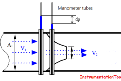
Flow across the orifice is proportional to the Sqrt of differential pressure across the orifice plate.
Lower β will have a higher pressure drop across the orifice because the orifice hole is small
Higher β will have a lower pressure drop across the orifice because the orifice hole is bigger. Sometimes it is difficult to measure lower differential pressure by DP Transmitter (e.g. 30 mmH2O)
At Lower DP conditions (e.g. min flow case) the transmitter accuracy is lower. Refer to the DP Transmitter catalogs for further readings.
A higher DP range for Transmitter is preferred because it will have better accuracy, but it will have higher pressure drops across the orifice. Hence there is always a trade-off for selecting a calibration range to satisfy accuracy and PPL (permanent pressure loss).
Permanent pressure loss is proportional to calibrated DP. Higher the calibrated DP, Higher the PPL (which may not be acceptable to process sometimes). In general, the allowable permanent pressure drop across is 0.1 to 0.2 bar.
Approximate PPL at Calibrated condition = (1 – β^1.9)*differential pressure Calibrated
Approximate PPL at Actual condition = (1 – β^1.9)*differential pressure actual.
Most DP transmitter has a rangeability of 100:1 which results in a flow rangeability of 10:1 [Sqrt(100)].
Furthermore, the initial 10% of DP transmitter readings are more erroneous. So Practically DP Transmitter’s usable rangeability is 100% (Max):10% (min) which equals 10:1 so the flow rangeability comes to around 3.16:1, so in industry, the orifice is used for flow rangeability up to 5:1, this is a conservative design.
Where minimum flow condition or turndown case is not so important, the orifice can be used/selected up to 10:1 flow rangeability.
It is advised to know all your project specification requirements to kick-start the sizing of the flow orifice. The most stringent requirement has to be respected (e.g. β is allowed in the range of 0.1 to 0.7 for flow orifice as per ISO 5167 part 2. However, some client specifications will have β range of 0.2 to 0.6)
Read Next:
- Flow Meter Calibration
- Pitot Tube Problems
- Flow Meter Verification
- MPFM Working Principle
- Flow Transmitter Questions