Inst ToolsInst ToolsInst Tools
  • Courses
  • Automation
    • PLC
    • Control System
    • Safety System
    • Communication
    • Fire & Gas System
  • Instrumentation
    • Design
    • Pressure
    • Temperature
    • Flow
    • Level
    • Vibration
    • Analyzer
    • Control Valve
    • Switch
    • Calibration
    • Erection & Commissioning
  • Interview
    • Instrumentation
    • Electrical
    • Electronics
    • Practical
  • Q&A
    • Instrumentation
    • Control System
    • Electrical
    • Electronics
    • Analog Electronics
    • Digital Electronics
    • Power Electronics
    • Microprocessor
  • Request
Search
  • Books
  • Software
  • Projects
  • Process
  • Tools
  • Basics
  • Formula
  • Power Plant
  • Root Cause Analysis
  • Electrical Basics
  • Animation
  • Standards
  • 4-20 mA Course
  • Siemens PLC Course
Reading: Optoisolator Working Principle
Share
Font ResizerAa
Inst ToolsInst Tools
Font ResizerAa
  • Courses
  • Design
  • PLC
  • Interview
  • Control System
Search
  • Courses
  • Automation
    • PLC
    • Control System
    • Safety System
    • Communication
    • Fire & Gas System
  • Instrumentation
    • Design
    • Pressure
    • Temperature
    • Flow
    • Level
    • Vibration
    • Analyzer
    • Control Valve
    • Switch
    • Calibration
    • Erection & Commissioning
  • Interview
    • Instrumentation
    • Electrical
    • Electronics
    • Practical
  • Q&A
    • Instrumentation
    • Control System
    • Electrical
    • Electronics
    • Analog Electronics
    • Digital Electronics
    • Power Electronics
    • Microprocessor
  • Request
Follow US
All rights reserved. Reproduction in whole or in part without written permission is prohibited.
Inst Tools > Blog > Electronic Devices & Circuits > Optoisolator Working Principle

Optoisolator Working Principle

Last updated: September 27, 2016 3:07 pm
Editorial Staff
Electronic Devices & Circuits
No Comments
Share
1 Min Read
SHARE

An optoisolator (also called optocoupler) is a device that uses light to couple a signal from its input

(a photoemitter e.g., a LED) to its output (a photodetector e.g., a photo-diode).

Optoisolator Working Principle

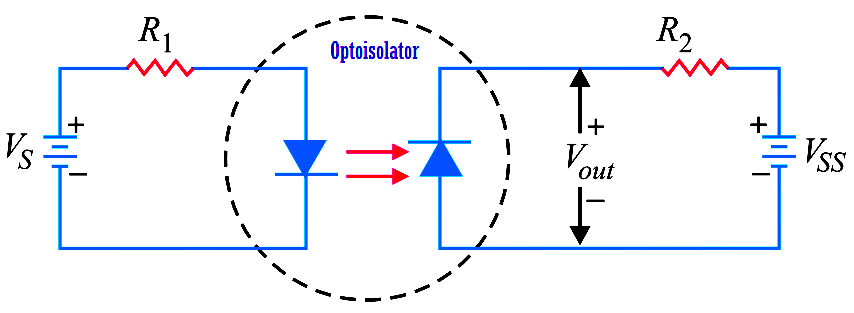
The above Fig. shows a LED-photo diode optoisolator. The LED is on the left and the photo-diode is on the right.  The arrangement shown in Fig. is referred to as optocoupling because the output from the LED circuit is coupled via light to the photo-diode circuit.  When the LED is energised, current flows through the LED.  The light from the LED hits the photo diode and sets up a reverse current through resistor R2.

The voltage across the photo-diode is given by :

Vout  = VSS – I R2

The output voltage depends on how large the reverse current is. If we vary the LED supply, the amount of light changes and this causes the photo diode current to change. As a result, Vout changes. The key advantage of an optoisolator is the electrical isolation between the input and output circuits; the only contact between the input and output circuits is the stream of light.

Don't Miss Our Updates
Be the first to get exclusive content straight to your email.
We promise not to spam you. You can unsubscribe at any time.
Invalid email address
You've successfully subscribed !

Continue Reading

Light Emitting Diode Operation
Electron Gun of Cathode Ray Tube
CRT Fluorescent Screen
Combining Independent Voltage Sources in Series
Transistor as a Switch Working Principle
Cathode Ray Tube Deflection System
Share This Article
Facebook Whatsapp Whatsapp LinkedIn Copy Link
Share
Leave a Comment

Leave a Reply Cancel reply

Your email address will not be published. Required fields are marked *

Stay Connected

128.3kFollowersLike
69.1kFollowersFollow
210kSubscribersSubscribe
38kFollowersFollow

Categories

Explore More

Difference between Schottky Diode and PN junction Diode
Dependent Voltage Source
Electronic Symbols
pi filter Operation
Full Wave Bridge Rectifier Peak Inverse Voltage
Combining Independent Current Sources in Parallel
Short Notes on Rectifiers & Filters
Basics of Ohm’s Law

Keep Learning

transistor-emitter-bias

Transistor Emitter Bias

Power MOSFET Safe Operating Area

Power MOSFET Safe Operating Area

Applications of Photo diodes

Applications of Photo diodes

schottky diode working principle

Schottky Diode Working Principle

Basic Transistor Amplifier Circuit Principle

Basic Transistor Amplifier Circuit Principle

Transistor Emitter Feedback Bias

Transistor Emitter Feedback Bias

Current Divider Rule

Current Divider Rule

transistor-biasing-circuits

Summary Of Transistor Bias Circuits

Learn More

Snubber Circuits

Thyristor Protection Circuits (SCR) – Types, Principle, Explanation

MCQ on Measurement and Instrumentation

250+ Electronic Measurements and Instrumentation MCQ Questions

Flapper nozzle system

Flapper Nozzle Questions

Transformers Questions & Answers Part-4

Transformers Questions & Answers Part-4

Difference between Standards and Codes

Difference between Standards, Codes, Specifications, Regulations

Serial Communication Data Transmission Modes

Serial Communication Data Transmission Modes

Creating CNC Program

Steps Followed Before Creating CNC Program

MEASURING AN NPT CONNECTION

NPT Connection Measurement Size

Menu

  • About
  • Privacy Policy
  • Copyright

Quick Links

  • Learn PLC
  • Helping Hand
  • Part Time Job

YouTube Subscribe

Follow US
All rights reserved. Reproduction in whole or in part without written permission is prohibited.
Welcome Back!

Sign in to your account

Username or Email Address
Password

Lost your password?