Inst ToolsInst ToolsInst Tools
  • Ask
  • Courses
  • Videos
  • Q & A
    • Interview
      • Instrumentation
      • Electronics
      • Electrical
      • Practical Questions
    • MCQ
      • Instrumentation MCQ
      • Electrical MCQ
      • Electronics MCQ
      • Control Systems MCQ
      • Analog Electronics MCQ
      • Digital Electronics MCQ
      • Power Electronics MCQ
      • Microprocessor MCQ
      • Multiple Choice Questions
  • EE
    • Electronics
      • Electronics Q & A
      • Electronic Basics
      • Electronic Devices & Circuits
      • Electronics Animation
      • Digital Electronics
    • Electrical
      • Electrical Basics
      • Electrical Q & A
      • Power Electronics
      • Electrical Machines
      • Electrical Animation
      • Power Systems
      • Switchgear & Protection
      • Transmission & Distribution
  • Measure
    • Control Valves
    • Calibration
    • Temperature
    • Pressure
    • Flow
    • Level
    • Analyzers
    • Switches
    • Vibration
    • Solenoid Valve
  • Control
    • PLC Tutorials
    • Control Systems
    • Safety Instrumented System (SIS)
    • Communication
    • Fire & Gas System
  • More
    • Design
    • Tools
    • Animation
    • Basics
    • Formulas
    • Standards
    • TextBooks
    • Common
    • Software
    • Excel Tools
    • Erection & Commissioning
    • Process Fundamentals
    • Videos
    • Books
Search
All rights reserved. Reproduction in whole or in part without written permission is prohibited.
Reading: Optocouplers Working Principle
Share
Notification Show More
Font ResizerAa
Inst ToolsInst Tools
Font ResizerAa
  • Courses
  • PLC Tutorials
  • Control Systems
Search
  • Ask
  • Courses
  • Videos
  • Q & A
    • Interview
    • MCQ
  • EE
    • Electronics
    • Electrical
  • Measure
    • Control Valves
    • Calibration
    • Temperature
    • Pressure
    • Flow
    • Level
    • Analyzers
    • Switches
    • Vibration
    • Solenoid Valve
  • Control
    • PLC Tutorials
    • Control Systems
    • Safety Instrumented System (SIS)
    • Communication
    • Fire & Gas System
  • More
    • Design
    • Tools
    • Animation
    • Basics
    • Formulas
    • Standards
    • TextBooks
    • Common
    • Software
    • Excel Tools
    • Erection & Commissioning
    • Process Fundamentals
    • Videos
    • Books
Follow US
All rights reserved. Reproduction in whole or in part without written permission is prohibited.
Inst Tools > Blog > Electronic Devices & Circuits > Optocouplers Working Principle

Optocouplers Working Principle

Last updated: September 3, 2019 7:17 am
Editorial Staff
Electronic Devices & Circuits Electronics Animation
No Comments
Share
3 Min Read
SHARE

What is optocoupler?

 An optocoupler is an optical link and it connects two circuits via this link.
The optical link is contained within a chip. A Light Emitting Diode inside the chip shines on a photo-diode, photo-transistor or other photo device.
When the photo device sees illumination, the resistance between its terminals reduces. This reduced resistance can activate another circuit.
Optocoupler Working Animation

An optocoupler uses an LED optically coupled to a photodiode or a phototransistor in a single package.

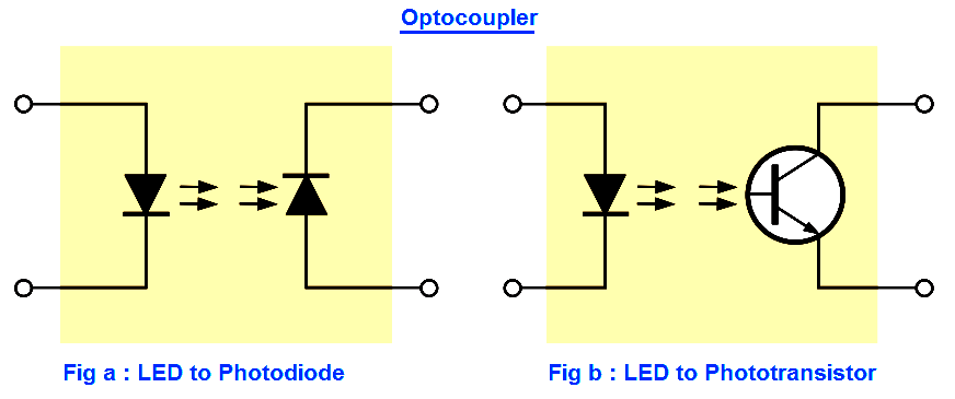
Two basic types are LED-to-photodiode and LED-to-phototransistor, as shown in Figure.

Optocoupler Principle


Optocouplers are used to isolate sections of a circuit that are incompatible in terms of the voltage levels or currents required.

For example, they are used to protect hospital patients from shock when they are connected to monitoring instruments or other devices.

They are also used to isolate low-current control or signal circuits from noisy power supply circuits or higher-current motor and machine circuits.

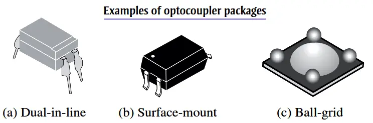
Examples of typical packages are shown in Figure.

Different Optocoupler Packages


OptoCoupler Operation Animation

OptoCoupler Animation


The LED requires 1mA to 15mA.

What does this mean?

If the current-limiting resistor connected to the LED has a high value, only a small current will flow through the LED and it will not glow very brightly. (The LED is inside the chip – you cannot see it).

The transistor will not turn on very much and the resistance between the collector-emitter terminals will be fairly HIGH. The output voltage will remain fairly HIGH.

As the current through the LED increases, (the current-limiting resistor is reduced in value) the LED will glow brighter and the transistor will turn on harder. The output voltage in the diagram above will reduce.

If the current through the LED is allowed to rise and fall, the output voltage of the circuit above will fall and rise.

If the current through the LED changes instantly from zero to say 15mA, the output will change from HIGH to LOW. This is the principle of SWITCHING or passing a DIGITAL SIGNAL.

Don't Miss Our Updates
Be the first to get exclusive content straight to your email.
We promise not to spam you. You can unsubscribe at any time.
Invalid email address
You've successfully subscribed !
Electronic Symbols
Transistor Emitter Feedback Bias
LC Tuned circuit Working Animation
CRT Fluorescent Screen
Series and Parallel Resistors
Share This Article
Facebook Whatsapp Whatsapp LinkedIn Copy Link
Share
Leave a Comment

Leave a Reply Cancel reply

Your email address will not be published. Required fields are marked *

Stay Connected

128.3kFollowersLike
69.1kFollowersFollow
208kSubscribersSubscribe
38kFollowersFollow

Categories

Recent Comments

  • Guifty Shimica on Top Non-PLC Certification Courses for Automation Professionals
  • Guifty Shimica on Top Non-PLC Certification Courses for Automation Professionals
  • MIHARITSOA Aina Sitraka on Top Non-PLC Certification Courses for Automation Professionals
  • Vaishnavi on Free Instrumentation Course for Trainee Engineers

Related Articles

Comparison of MOSFET and BJT

Comparison of MOSFET and BJT

Shockley Diode Working Principle

Shockley Diode Working Principle

Laser Diode Working Principle

Laser Diode Working Principle

p-type-semiconductor

N Type and P Type Semiconductors

Full Wave Rectifier Peak Inverse Voltage

Full Wave Bridge Rectifier Peak Inverse Voltage

Transistor Collector Characteristic Curves

Transistor Collector Characteristic Curves

Current Limiting Resistor

Resistors Principle & Applications

Choke Input Filter Operation

Choke Input Filter Operation

More Articles

Difference Between Sensor and Transducer

What is the Difference Between Sensor and Transducer?

Transducers MCQ

Transducers MCQ

Pressure Regulator with Flapper-Nozzle Principle

Pressure Regulator with Flapper-Nozzle Principle

PLC Latched Circuit Example

PLC Latching Function

Electrical Machines Objective Questions

Electrical Machines MCQ Series 11

Closed-tank-DP-Level-Transmitter-with-wet-leg-Zero-elevation-Calibration

Closed tank DP Level Transmitter with wet leg Zero elevation Calibration

Closed Tank Level Measurement using DP Transmitter

How can we use a DP Flow Transmitter for Level Measurement

Remote Seal Pressure Transmitter Temperature

Importance of Temperature in Remote Seal Pressure Transmitter

Follow US
All rights reserved. Reproduction in whole or in part without written permission is prohibited.
Welcome Back!

Sign in to your account

Username or Email Address
Password

Lost your password?