Design a PLC Ladder diagram for opposite acting control valves application with a real time process industry.
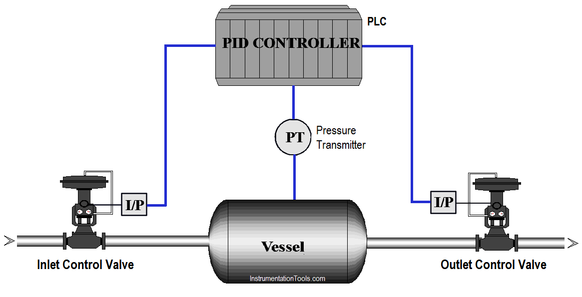
In chemical industry, chemical reactants were made using different vessels, in such applications sometimes we have to control the inlet flow and outlet flow based on pressure inside the vessel.
The inlet control valve and outlet control valve are used to maintain the vessel flow rates. Write PLC program for this application using ladder diagram language.

For this application, we use opposite control concept. Here we are considered reactor control example.
We have two control valves, inlet valve is used for chemical reactants control and output control valve is used for flow control.
Pressure transmitter is used for pressure measurement in the reactor/vessel. If the pressure is too low in the reactor, controller will open the inlet valve.
Assume Inlet valve is fully closed and outlet valve is fully open when controller output is 0% (opposite acting control). At 50% output of controller, both the valves are 50% open.
If controller output is 100%, inlet valve is fully open and outlet valve is fully closed.
Note : In PLC Logic we use only one PID controller for controlling both Input and Output Control Valves. Generally we use a SPLIT block after the PID controller output in PLC using programming. so we can connect the two control valves with separate analog output of the PLC. Hence you can calculate output range in PLC.
For this application, we used S7-300 PLC and TIA portal software for programming.
In the network, we configured standard parameters for PID function.
“Drive PID”.sRet.r_Ctrl_Td:-Saved derivative time or D gain for PID (0s).
Here we have taken pressure PID max output limit and minimum output limit. We considered here max limit for PID output 100 and minimum limit is 0.
Sampling time of the PID_Compact instruction r_Cycle is determined automatically and usually equivalent to the cycle time of the calling OB. Consider 0.1s for this application.
When PID enable (M61.0) is pressed PID block will be executed. As per SET point (MD500) it will generate output (0-27648) and according to actual pressure transmitter will give feedback (IW96) to PID.Manual enable (M61.1) is for manual operation and PID reset (M61.2) is for resetting the PID.
Activate Mode after CPU restart If sb_RunModeByStartup = FALSE, the controller will remain inactive after a CPU startup.
Here we calculated the PID output range for the inlet valve (reactants).It will be fully open when PID output reaches 100%.
Here PID output is calculated for outlet valve (Products). When PID output reaches 100% output, outlet valve is fully closed.
Note : Above application may be different from actual application. We can also make this application by using Stand-alone PID controller and current to pressure converters. This example is only for explanation purpose. We can implement this logic in other PLC software also. This is the simple opposite acting control application for the valves used in industry, we can use this concept in other examples also.
All parameters and graphical representations considered in this example are for explanation purpose only, parameters or representation may be different in actual applications. Also all interlocks are not considered in the application.
Author: Bhavesh
If you liked this article, then please subscribe to our YouTube Channel for PLC and SCADA video tutorials.
You can also follow us on Facebook and Twitter to receive daily updates.
Read Next:
In this article, a simple example will teach you the conversion from Boolean algebra to…
In this article, you will learn the PLC cooking timer example for kitchen automation using…
Learn an example PLC program to control a pump based on level sensors using ladder…
In the PLC timer application for security camera recording, when motion is detected then camera…
In this example, we will learn batch mixing with PLC ladder logic program using timer…
This PLC example on manufacturing line assembly is an intermediate-level PLC program prepared for the…
View Comments
Tag MD762 is not used on the program and MW762 is assigned two different symbolic names(PID OUTPUT-ANALOG & PID OUTPUTS FOR INLET VALVE)
How to write program for default set point 40% for control valve?