This article will discuss the Omron PLC project to control a fish farming system automation using the CX-Programmer Software. This system will automatically control the water flow in the fish pond, continuously monitor the pH level and water temperature, and control the feeding schedule. If water quality parameters such as pH or temperature deviate from preset values, the system will immediately give an alarm. With this automation, the fish farming process becomes more efficient and accurate.
Program Objective
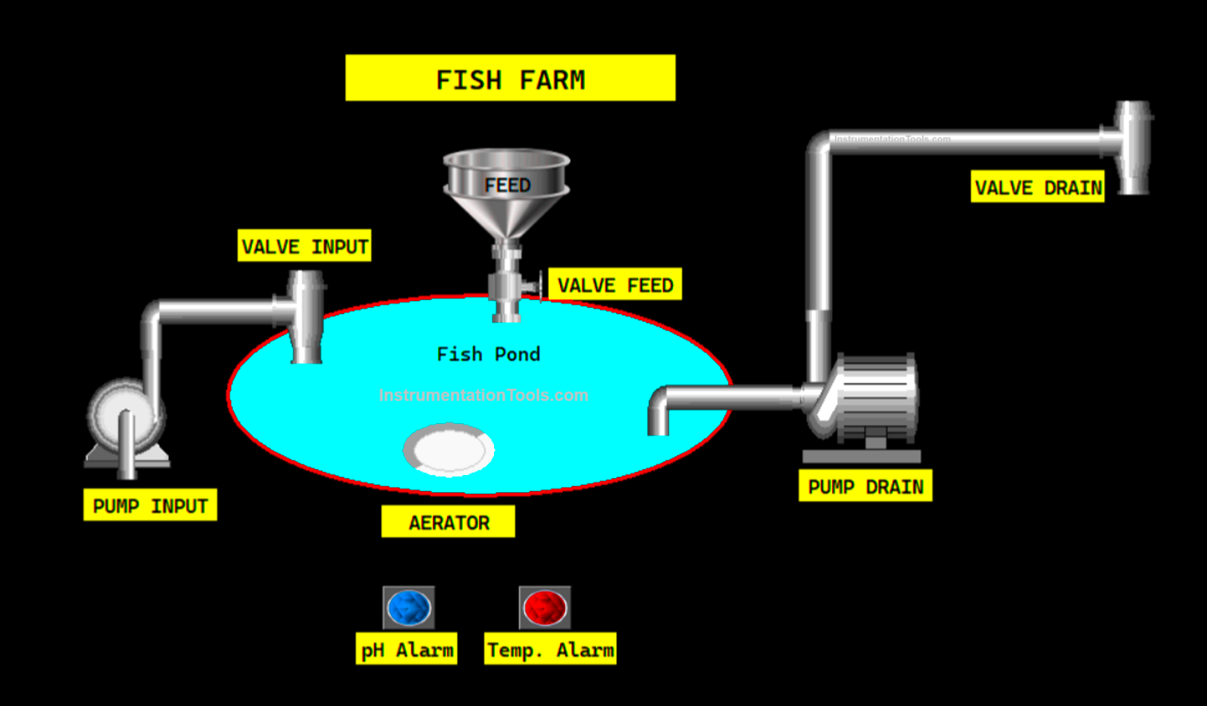
- When this system is running, the Aerator will turn ON to control air circulation in the water.
- Fish food will be given every 10-second interval. There will be a Valve that is used to control the feed dispensing process.
- The indicator alarm will turn ON if the pH value measured in the fish pond water is Greater Than 8 or Less Than 6.
- If the temperature value in the fish pond water is Above “33” degrees or Below “27” degrees, the Alarm Indicator will turn ON.
- This system also has a level sensor (HIGH and LOW) to monitor the water level in the fish pond.
- When the water level in the fish pond is below the level limit (LOW LEVEL), the water Pump will turn ON to fill the fish pond with water.
- When the water level in the fish pond exceeds the upper level limit (HIGH LEVEL), the water Pump will turn ON to reduce the water level in the fish pond.
Omron PLC Project
Project I/O Details
| S.No. | Comment | Input (I) | Output(Q) | Memory Words | Memory Bits | Timer |
| 1 | START | 0.00 | ||||
| 2 | STOP | 0.01 | ||||
| 3 | WATER_LEVEL_LOW | 0.02 | ||||
| 4 | WATER_LEVEL_HIGH | 0.03 | ||||
| 5 | AERATOR | 100.00 | ||||
| 6 | VALVE_FISH_FEED | 100.01 | ||||
| 7 | ALARM1 | 100.02 | ||||
| 8 | ALARM2 | 100.03 | ||||
| 9 | VALVE_INPUT_WATER | 100.04 | ||||
| 10 | PUMP_INPUT_WATER | 100.05 | ||||
| 11 | VALVE_DRAIN_WATER | 100.06 | ||||
| 12 | PUMP_DRAIN_WATER | 100.07 | ||||
| 13 | PV_WATER_PH | D0 | ||||
| 14 | WATER_TEMPERATURE | D1 | ||||
| 15 | TIMER1 | T0000 | ||||
| 16 | TIMER2 | T0001 | ||||
| 17 | TIMER3 | T0002 | ||||
| 18 | TIMER4 | T0003 | ||||
| 19 | SYSTEM_ON | W0.00 |
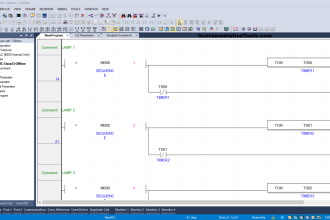
Fish Farm Automation Tutorial
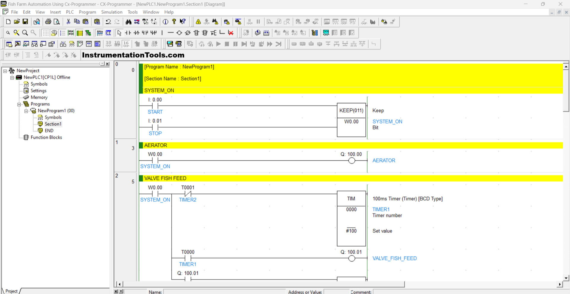
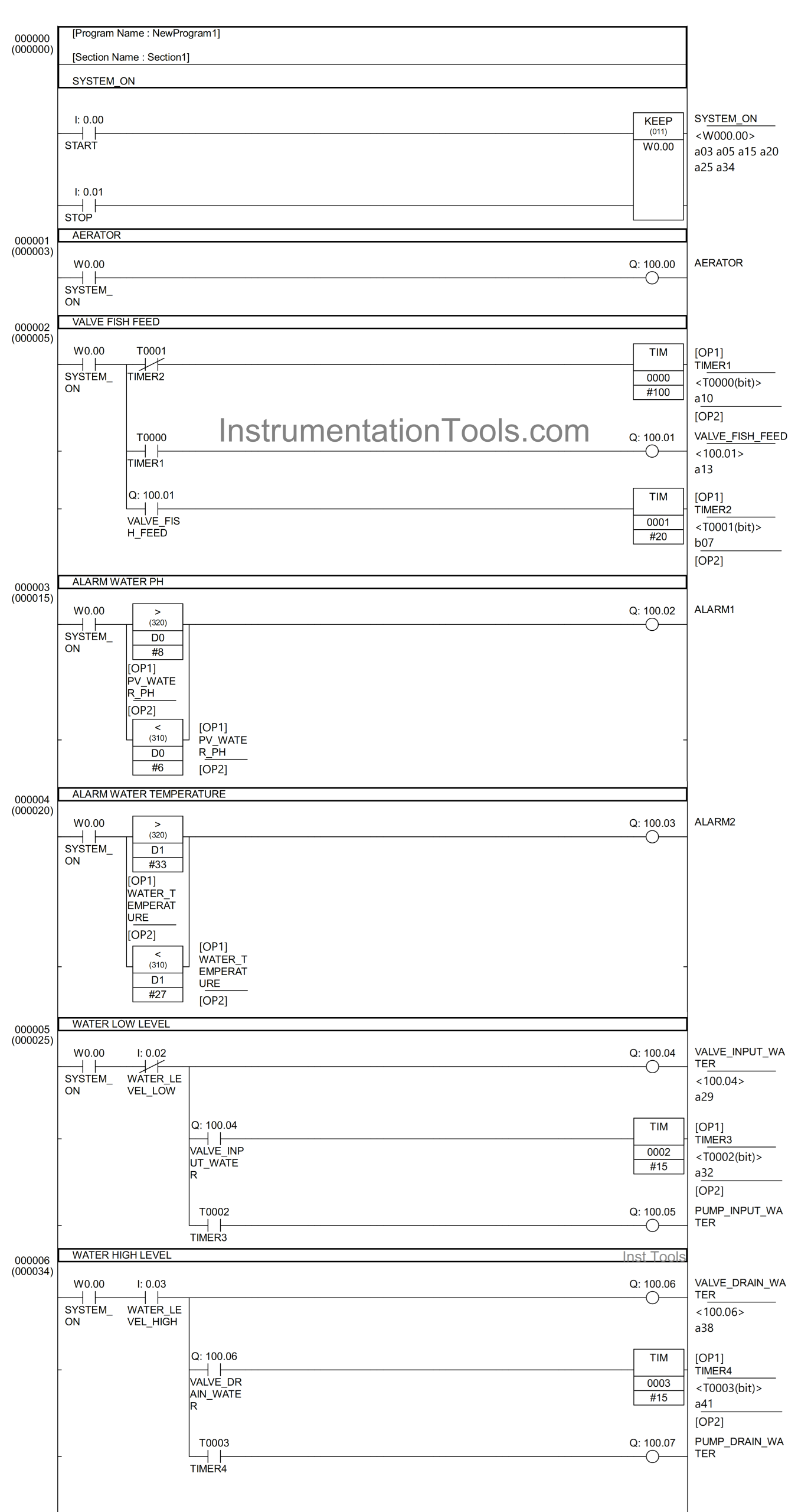
RUNG 0 (SYSTEM_ON)
In this Rung, when the PB_START (0.00) button is Pressed, the memory bit SYSTEM_ON (W0.00) will be in the HIGH state. Because it uses the KEEP(011) instruction, the memory bit SYSTEM_ON (W0.00) will remain in the HIGH state even though the PB_START (0.00) button has been Released.
The memory bit SYSTEM_ON (W0.00) will be in the LOW state if the PB_STOP (0.01) button is Pressed.
RUNG 1 (AERATOR)
In this Rung, when the NO contact of the memory bit SYSTEM_ON (W0.00) in the HIGH state, the AERATOR (100.00) Output will be ON.
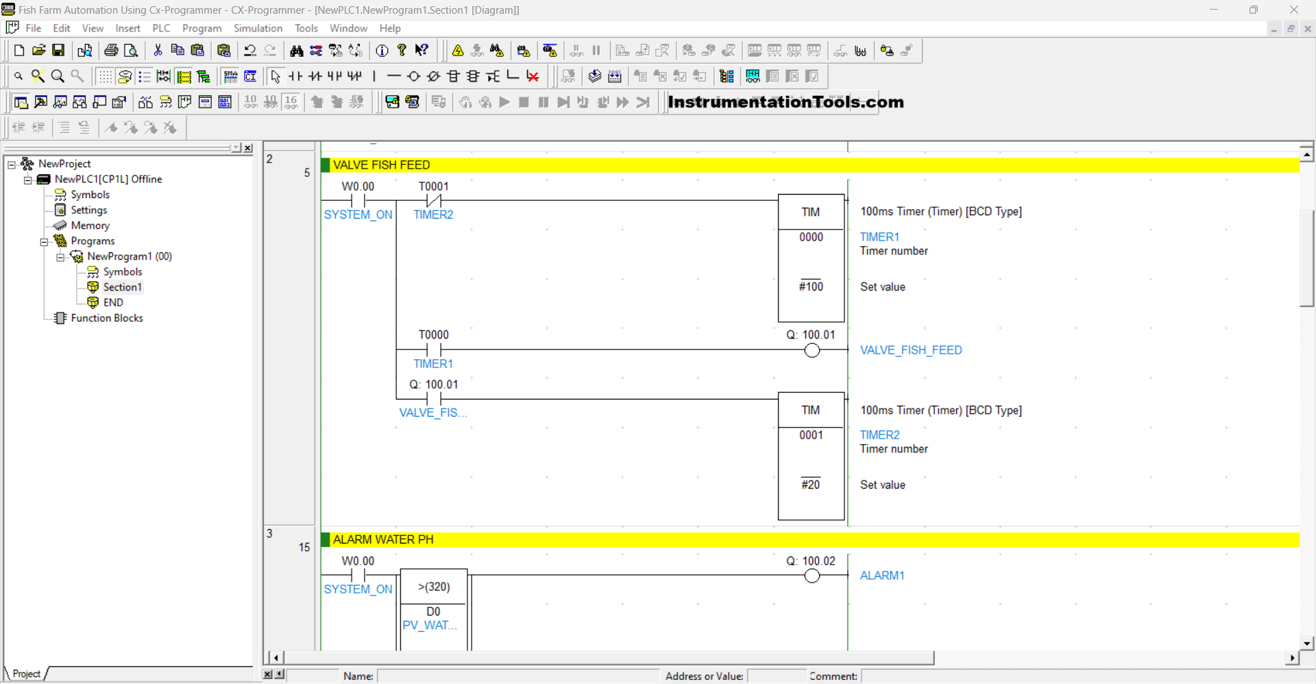
RUNG 2 (FISH FEED VALVE)
In this Rung, when the NO contact of memory bit SYSTEM_ON (W0.00) is in the HIGH state, the TIMER1 (T0000) Timer will Start counting up to 10 seconds. When Timer TIMER1 (T0000) has Finished counting, the Output VALVE_FISH_FEED (100.01) will become OPEN and Timer TIMER2 (T0001) will Start counting up to 10 seconds.
When Timer TIMER2 (T0001) has finished counting, Timer TIMER1 (T0000) will be Reset and the Output VALVE_FISH_FEED (100.01) will return to CLOSE.
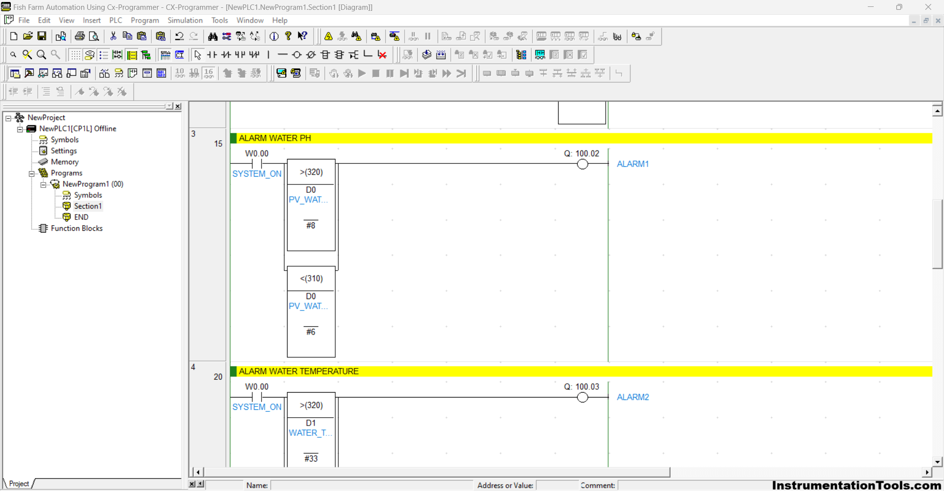
RUNG 3 (WATER PH ALARM)
In this Rung, when the NO contact of the memory bit SYSTEM_ON (W0.00) is in the HIGH state and the value in the memory word PV_WATER_PH (D0) is Greater Than “8” or Less Than “6”, then the Output ALARM1 (100.02) will be ON.
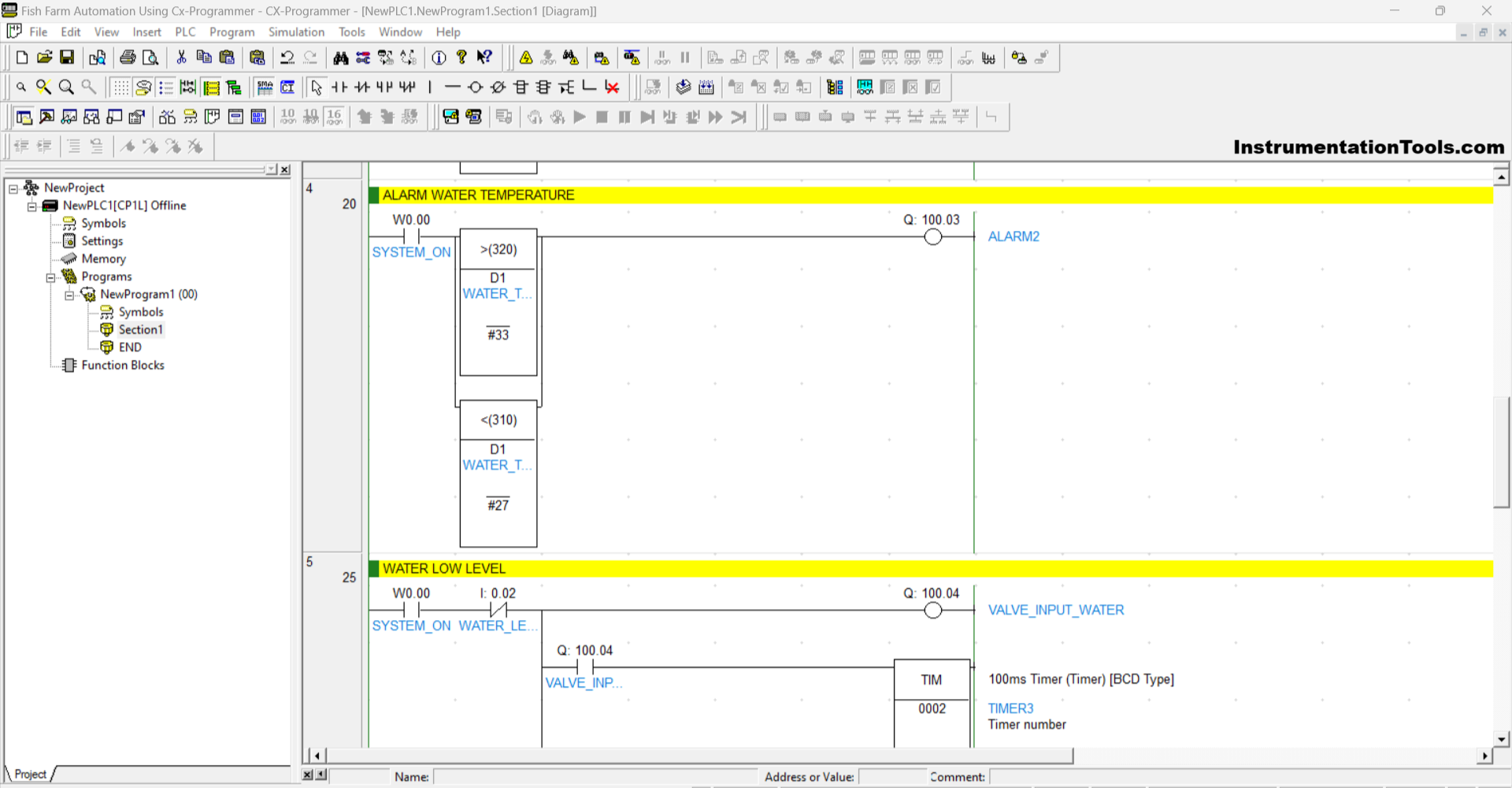
RUNG 4 (ALARM WATER TEMPERATURE)
In this Rung, when the NO contact of the memory bit SYSTEM_ON (W0.00) is in the HIGH state and the value in the memory word WATER_TEMPERATURE (D1) is Greater Than “33” Or Less than “27”, then the Output ALARM2 (100.03) will be ON.
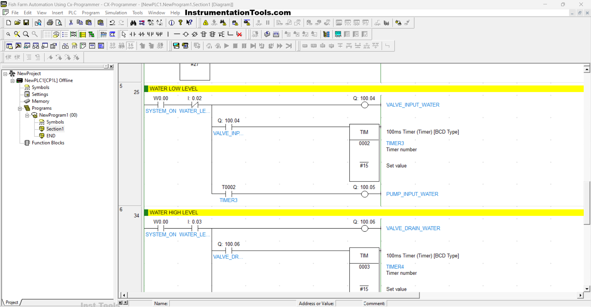
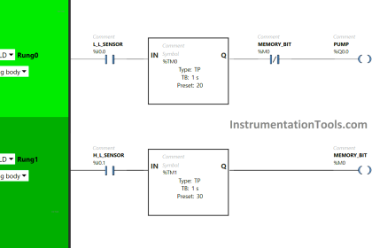
RUNG 5 (WATER LOW LEVEL)
In this Rung, when the NO contact of the memory bit SYSTEM_ON (W0.00) is in the HIGH state, the Output VALVE_INPUT_WATER (100.04) will become OPEN and the TIMER3 (T0002) Timer will Start counting up to 1,5 seconds.
When Timer TIMER3 (T0002) has Finished counting, the PUMP_INPUT_WATER (100.05) Output will become ON.
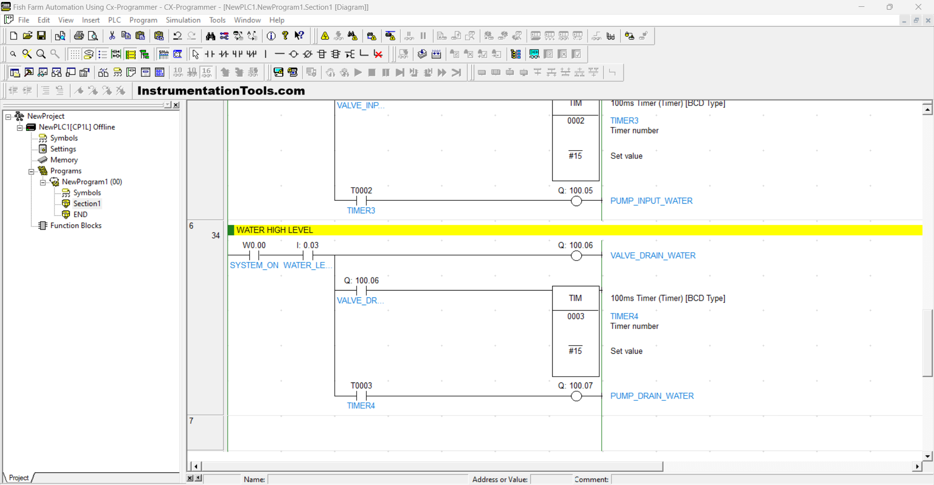
RUNG 6 (WATER HIGH LEVEL)
In this Rung, when the NO contact of the memory bit SYSTEM_ON (W0.00) is in the HIGH state, the Output VALVE_DRAIN_WATER (100.06) will become OPEN and the TIMER4 (T0003) Timer will Start counting up to 1,5 seconds.
When Timer TIMER4 (T0003) has Finished counting, the PUMP_DRAIN_WATER (100.07) Output will become ON.
Read Next:
- How to Choose PLC Programming Software?
- Siemens LOGO PLC Programming Course
- How to Download GX Works Software?
- Which Connection is Best for PLC Panel?
- Why is 24 Volts Commonly used in PLC?