This article discusses a dual conveyor product packaging system using Omron PLC logic. The system aims to automate the process of filling products into boxes in an orderly and efficient manner. There will be two conveyors: one to drop the products into the boxes and another to move the boxes. Products will only be dropped when a box is positioned underneath. This process runs automatically and repeatedly. The system will also record the number of boxes that have been filled.
Program Objective
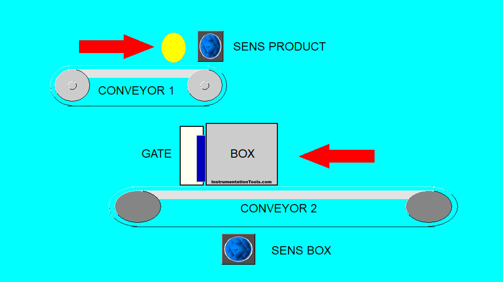
- Conveyor 1 (top) is used to transport products and drop them into a box, while Conveyor 2 (bottom) is positioned below Conveyor 1 and is equipped with a retaining gate to control the movement of the box.
- The box will collect the products dropped by Conveyor 1, while Conveyor 2 operates continuously to move the box forward.
- Once the box is filled with a certain amount of products, the system will stop Conveyor 1, open the gate, and allow the box to continue moving.
- The gate will close again once it detects a new box ready to be filled.
- After the gate is closed, Conveyor 1 will reactivate to drop products into the next box, and this cycle repeats automatically.
Product Filling and Box Movement Control Using PLC
IO Mapping Details
| S.No. | Comment | Input (I) | Output (Q) | Memory Bit | Memory Word |
|---|---|---|---|---|---|
| 1 | START | 0.00 | |||
| 2 | STOP | 0.01 | |||
| 3 | SENS_BOX | 0.02 | |||
| 4 | SENS_PRODUCT | 0.03 | |||
| 5 | CONVEYOR_PRODUCT | 100.00 | |||
| 6 | CONVEYOR_BOX | 100.01 | |||
| 7 | GATE_BOX | 100.02 | |||
| 8 | COUNTER PRODUCT | D0 | |||
| 9 | COUNTER BOX | D1 | |||
| 10 | SYSTEM_ON | W0.00 | |||
| 11 | ILC_PRODUCT | W0.01 |
Programming
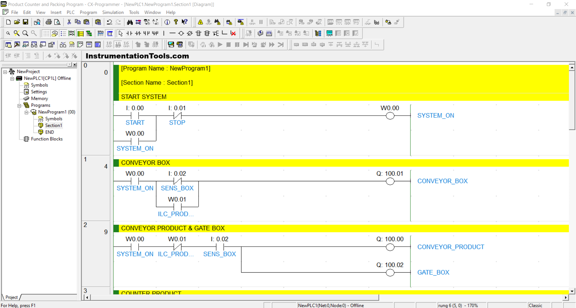
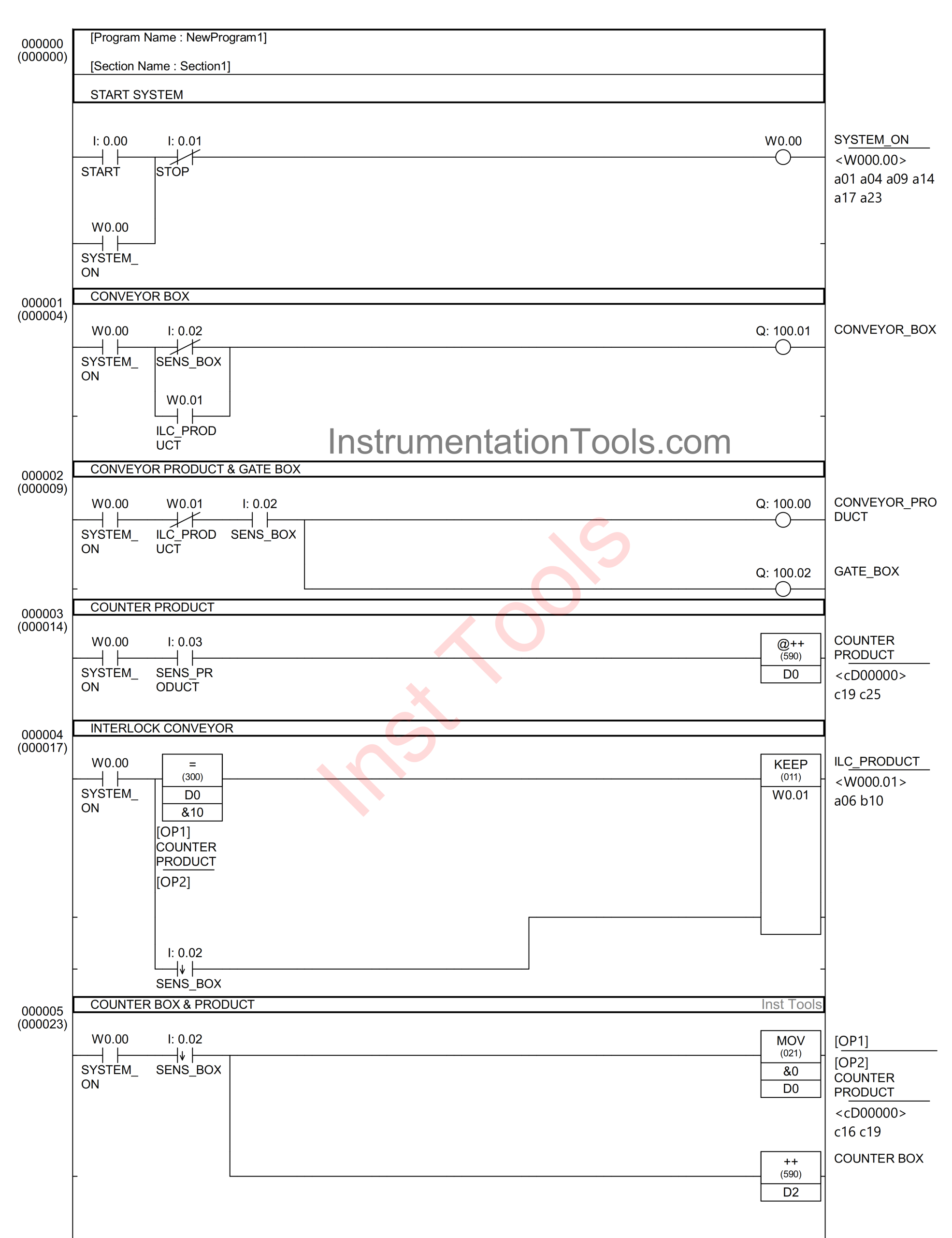
RUNG 0 (START SYSTEM)
In this rung, if the START (0.00) button is pressed, the memory bit SYSTEM_ON (W0.00) will be set to a HIGH state. Because it uses latching, the memory bit SYSTEM_ON (W0.00) will remain in a HIGH state even after the START (0.00) button is released.
The memory bit SYSTEM_ON (W0.00) will return to a LOW state when the STOP (0.01) button is pressed.
RUNG 1 (CONVEYOR BOX)
In this rung, if the NO contact of the memory bit SYSTEM_ON (W0.00) is in a HIGH state and the NC contact of the SENS_BOX (0.02) sensor is also in a LOW state, then the output CONVEYOR_BOX (100.01) will turn ON.
Alternatively, if the NO contacts of the memory bits SYSTEM_ON (W0.00) and ILC_PRODUCT (W0.01) are in a HIGH state, the CONVEYOR_BOX (100.01) output will also turn ON.
RUNG 2 (CONVEYOR PRODUCT & GATE BOX)
If the NO contacts of the memory bit SYSTEM_ON (W0.00) and the SENS_BOX (0.02) sensor are in a HIGH state, then the CONVEYOR_PRODUCT (100.00) and GATE_BOX (100.02) outputs will turn ON.
When the NC contact of the memory bit SYSTEM_ON (W0.00) is in a HIGH state, the CONVEYOR_PRODUCT (100.00) and GATE_BOX (100.02) outputs will turn OFF.
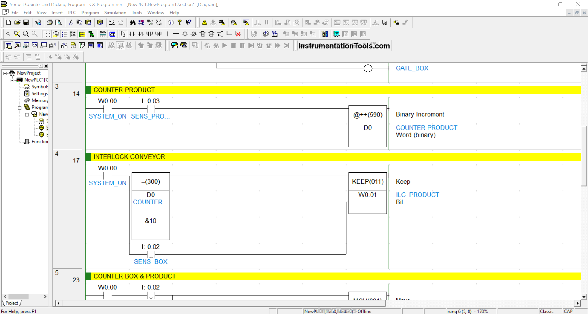
RUNG 3 (PRODUCT COUNTER)
When the NO contact from the memory bit SYSTEM_ON (W0.00) and the sensor SENS_PRODUCT (0.03) are in a HIGH state, the value in the memory word COUNTER_PRODUCT (D0) will increase (+1), because it uses the Binary Increment/@++ (590) instruction.
RUNG 4 (CONVEYOR INTERLOCK)
When the NO contact from the memory bit SYSTEM_ON (W0.00) is in a HIGH state and the value of the memory word COUNTER_PRODUCT (D0) is Equal to “10”, the memory bit ILC_PRODUCT (W0.01) will turn to a HIGH state.
Additionally, when the NO contact from the sensor SENS_BOX (0.02) is in a HIGH state, the memory bit ILC_PRODUCT (W0.01) will change to a LOW state.
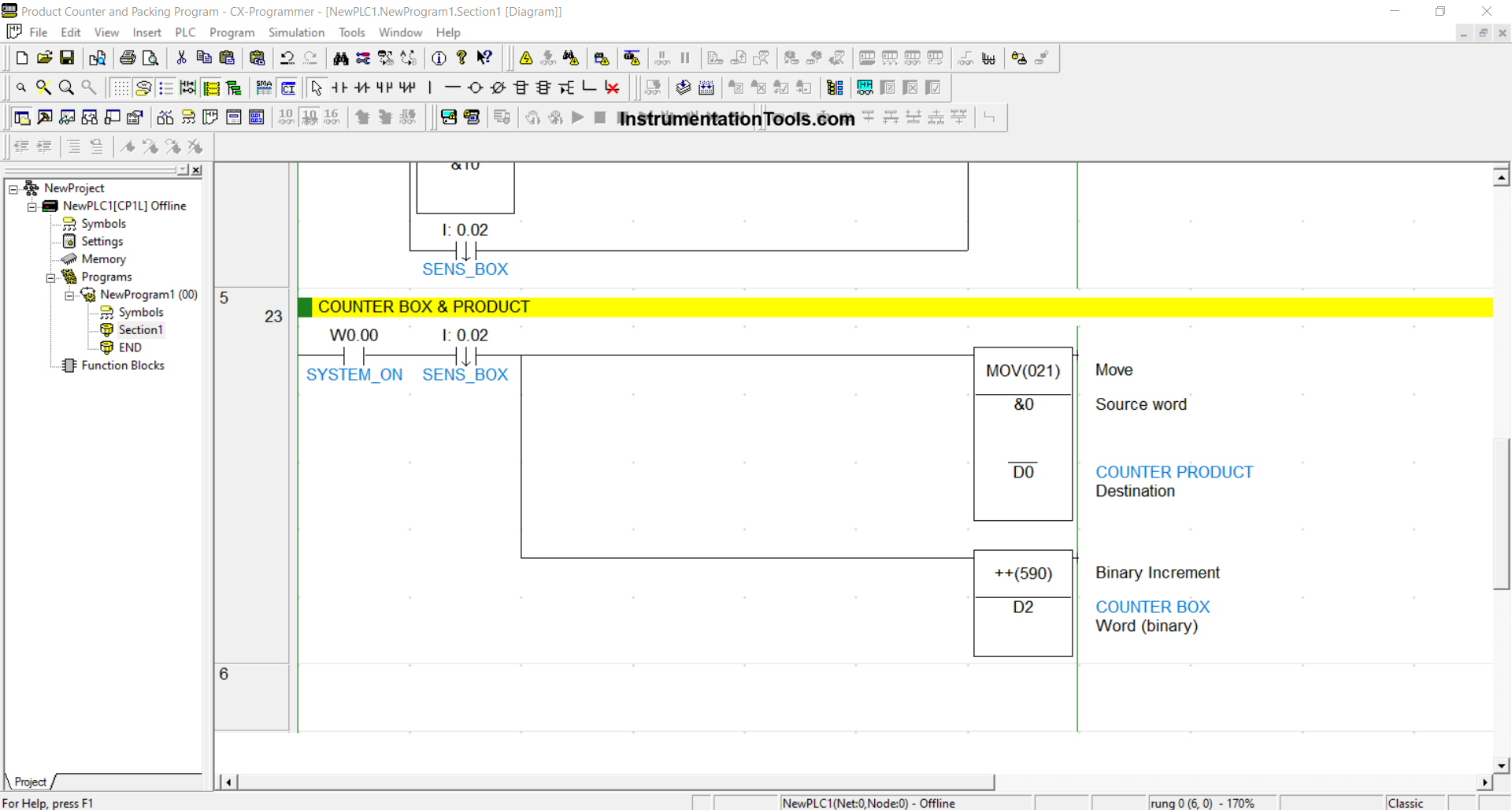
RUNG 5 (COUNTER BOX & PRODUCT)
When the NO contact of the memory bit SYSTEM_ON (W0.00) and the sensor SENS_BOX (0.02) are in a HIGH state, the value in the memory word COUNTER PRODUCT (D0) will be reset to zero “0”.
Additionally, the value in the memory word COUNTER BOX (D2) will increase (+1), because it is using the Binary Increment instruction / @++(590).
Read Next:
- From Boolean Algebra to PLC Logic Conversion
- PLC Programming Example on Timers Function Block
- PLC Programming for Boolean Expression with Example
- How to Blink Lights in Ladder Logic with Programming
- Create a PLC Ladder Logic based on a Digital Logic Circuit